


PlayfulWolfCub
-
Posts
636 -
Joined
-
Last visited
Content Type
Profiles
Forums
Gallery
Articles
Media Demo
Posts posted by PlayfulWolfCub
-
-
Erv over at the RPF (& creator of the awesome BlasterCore) just replied to me with this:
"I haven't been further in my investigations. Most people I've talked too are positive that this unit probably comes from military RF equipment. Many suggested an IF stage in a radar or something like this. Next step would be to visit a specialist and/or a junkyard dedicated to those parts to put a final point to that mystery.
As it's been seen in several props, there's a chance it was installed in those changeable aircraft racks that were gutted. That would explained why they got so many of them. The construction of the racks suggest the military use too (def not consumer electronics)
The number of pins of the valve socket don't provide so many choices for the valve type, due to the period of use, hence EF92. I have no doubt about the distributed amp topology neither for the use of the device : It's can't be audio (as confirmed by other people) as it's a super linear + *wide* bandwidth amp for RF instruments (radar, video, ILS why not). This is also (with no surprise) it's found in oscilloscopes as it's exactly the same purpose (large BW and linearity)."
I have no idea what most of that means as I'm no electrician but it gives us some more words & ideas to Google! lol

-
Thanks Playful Wolf Cub for contacting me!
Really glad you've joined us, Chris! I'm sure we can solve this mystery!
I started this thread just to talk about the 3 capacitors (or "fuses" as I then called them) but now I really want to pinpoint exactly what these parts are!
I feel I should repeat that I love the awesome cylinders that Russ made, based on your design and I mean no criticism at all by looking to get slightly more screen accurate.
Photos on eBay show that TCC is the English company that made "Metalmite". They also made the Metalcap, Metalmold & Metalpack series. I haven't found anything with a "K".
I've got an eBay autosearch on for Metalmite. Could you please post the photo that shows the TE" ?
I've bought the capacitors that Andy19422 found on ebay during his research on this subject. If there's a K on them I'll be extremely happy but either way I think they'll look really nice on my genuine parts E11 build.
(I've highlighted in red the sections that match quite closely)My suggestion that they went through the mounting bracket is based on this Mouse Droid photo - I've superimposed some more "ghost" TCCs onto it to show what I mean. I see no way the bottoms of the capacitors would be visible otherwise.
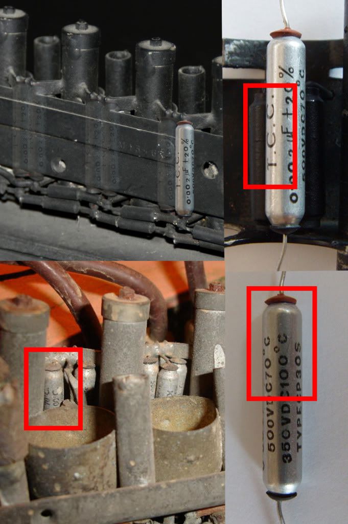
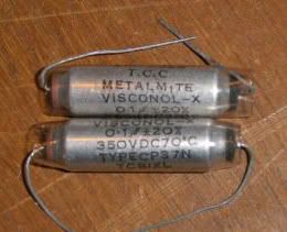
The picture below is of different capacitors to show that TCC made Metalmite
If the parts are from British military equipment (RAF or otherwise) I think there's it's likely that some British militaria/antique audio collectors will have the original equipment. There's a large militaria fair near me every 3 months (which is where I just bought my Sterling). If we identify what these parts are I can ask the dealers to keep their eyes open for them.
Has anyone (or could anyone) ever been able to get close to the Mouse Droid to take a cast of the parts? :ninja:
-
I'm not sure why I think this but I thought the screws they used to hold the scope onto the rail were hexagonal and brass....?
Sorry for any confusion if I'm wrong.
There were so many versions maybe some did and some didn't..?
John
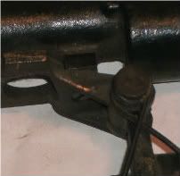
That's exactly it John - the hex ones are for the M19 (& similar) mounting bracket & the round ones for the M38 (& similar) mounting bracket. here's a fuzzy pic ot the M38 mounting bracket open. You'll see the round screw is recessed and would be impossible to reach with a spanner. The M19 bolts are proud of the surface (sorry, I don't have a pic)
 I
II've actually had some success with finding screws. I found some in a small ironmongers with the correct thread but the wrong length & wrong head size. They're solid brass & will be relatively easy to machine down to the dimensions Marv posted above. The ironmonger doesn't know what the thread is type is - he just found them in a shipment of clearance stock - he won't be getting any more so I bought the boxful in case future E11 scope owners want to buy accurate repro mounting screws.
I'll post pics when I've machined a pair down.
I'd still like some originals for total authenticity though
-
I just heard back from a vintage radio expert & these are his thoughts:
Hi Andy
I was asked about something simular about 5 years ago. But that one was painted gold.
I suspect the unit is WW11 Military and part of a bigger unit as its not a radio etc as such but a repetative line of circuits.
TCC were english but apart ftom that there is nothing else I can say about it
During the 50/60s the uk was flooded with government surplus electronics. This is a typical chassis from that period and they were bought by hobyists who either used the components to make something else or got the units working.
I suspect that the chassis in the picture is part of a radar or navigation system.
The bolt on capacitors I have not seen for years in new equipment. Remember technology has moved on and the size has decreased. There are no suppliers I know of who would have this old stock and they don't store very well.
The last aircraft in the RAF to carry such equipment retired some 30 years ago so the chances of picking any up are minimal.
You would probably be better off making your own from ally tube.
Maurice
Interesting stuff! Naturally I've thanked him profusely and promised to let him know if we eventually identify it
-
On 11/1/2011 at 12:17 PM, TK Bondservnt 2392 said:
the suggested center cells below are way too long!
russ has his scales correct!

you can't fault russ rep's scale... as this also must be in scale with the top of the magazine well on the sterling.
the capacitors are the correct type, just too long!
you can clearly see that rus rep has his scales correct when you look at the images above it.
I'm certainly not meaning to "fault" Russ's work, Vern. The template I made independently from him by measuring the available images is extremely simliar and his cylinder units are beautifully designed and made. I don't think he'd claim that they're 100% screen accurate in every detail though. Wouldn't it be great if we could finally (after 34 years!) feel we've got as totally screen-accurate power cylinders as possible (short of taking a cast from the Mouse Droid, which I don't see happening) for our E11 builds?
To achieve that level of accuracy we may need to alter existing designs but I mean no disrespect at all to anyone's efforts and I would hope that no-one wil take offence to me proposing that new designs are slightly more accurate.
The capacitors seem to fit perfectly when you notice that they pass through the rear plate just like the 2 larger capacitors either side of them:
On 10/31/2011 at 3:51 PM, PlayfulWolfCub said:If they're 26mm from where the connecting wire enters the brown cap then they'd sit on my draft Cylinder plan like this (not taking into account perspective). It's a plan I've made taking measurements from ref photos and it seems very similar to Russ's which I was pleased about - seeing how much independent plans agree is a good way of checking authenticity.


I suspect the capacitors will turn out to be exactly what was used on the E11s, Mouse Droid & Landspeeder. I'll have a better idea when I've received them from Andy19422 and I've incorporated them into a 3D model. (NB - My above template isn't final & isn't 100% accurate - it's just to give an impression of how the capacitors might fit)
-
Cool find! ...and now I've seen that digital calipers are only £6.99 on ebay I want some whether I need them or not! lol
-
or valve as i mentioned earlier

Cheers Geordie - wasn't meaning to skim over your input. Is a "valve" another word for "radio vacuum tube" or is it a different component entirely? I know guitarists have tube amps and valve amps but I don't know if they're the same thing. Like I said I think I need a crash course in vintage electronics just for this project! lol
This old radio (as in com radio) has several coax sockets internally for signal transfer.
"Com radio" - as in communciations? So does the inclusion of this socket suggest it's original purpose? Or at least rule some purposes out?
This is a fun investigation though it'd be easier to phone George (Lucas) and ask him to take a cast from the top of his Mouse Droid for us! lol
I'm puzzled as to why official repro E11s that have his endorsement aren't more accurate - in various areas but particularly the Power Cells!
-
I think you'll find that's my mistake.... I was measuring so many dimensions I must have got it wrong.......

I see your location is the UK, sskunky. I'm a tad jealous - where did you get an intact barrel from? (especially one from the very rare Sterling 8.5mm SMG!!!
)Unless .6 of an inch diameter difference will drive you crazy I think you'll be ok!
If I was going to be really obsessive I'd mention that the thick layers of paint that a Sterling is treated with will have altered most dimensions, including vent holes.

However I'll restrict myself to saying that one way of checking measurements is whether they equate exactly to an imperial measurement commonly used for fabrication since the machining tools will have been Imperial not Metric. I'm sure you've already thought of that but it took me quite a long time to realise it when I started making my plans.
I might buy some calipers off ebay so I can double-check the template measurements. Are you aiming for a particular date you like them totally finished & released by?
I'm using Illustrator for "The Best Power Cell template EVER!" but I've never tried extrude or bevel - I's got a new toy!!!
-
Ok, so to sum up what we've got so far:
A - large capacitor in an aluminium or tin case
B - small capacitor
C - socket for 7 pin radio vacuum tube (aka radio tube)
D - small capacitor shielded in tube
E - Male coaxial cable socket (I thought this too but I'm not sure why it'd be sitting among the innards of an amplifier (if that's what this is) rather than on the outside cover.)
F - Resistors (Finally I have an actual resistor involved! lol)
I think that's all the parts accounted for. I'll keep trying to locate original large capacitors (A) or modern casings of the same dimensions.
My Power cell designing is on hold till I receive the capacitors from Andy19422 since I'm sure they are the correct size & I'm much happier working on models with real objects rather than in PC software once I've got a rough idea of sizes.
-
On 10/31/2011 at 4:31 PM, Locitus said:
Btw... the small resistor you've got test mounted on the russrep cylinders isn't a resistor, it's a capacitor. Note the "0.002 uF" that means micro Farad. Resistors are measured in Ohm.
That's a really important distinction - thanks!!! (Though that's Andy19422's photo - I don't want to be taking credit for his research & finding of the capacitors)
So, in the following labelled pic what do you think each part's name & function is?
It looks to me like D is another capacitor but why would it need a shield around it?
E looks like some type of lead would attach to it -
& what do the parts at F look like they do? I know they got cut off for the E11 Power Cells but I'm hoping to track down an original part A
Exciting stuff!

-
I noticed you've got the central muzzle hole marked as 8.5mm. I've just measured an inert 9mm round & it is indeed 9mm (the casing is 10.85mm).
We all know a laser blast is 8.5mm wide and fits perfectly but, if we ever forget to plug our power cells in to charge the night before (& who hasn't done that?!?) it'd be handy to be able to use the old-fashioned gunpowder & projectile way of keeping those rebel scum down!

-
I've copied my conversation with Andy14922 into this post to keep things tidier:
Andy19422
Lieutenant
-

- Member
-

- 113 posts
- Name:andy
Posted 28 October 2011 - 07:46 PM
Hi Andy, great minds think alike
 After a lot of searching I think I found almost the same vintage resistors, If you check the two pics most of the labelling matches up.

By andy19422 at 2010-09-01

By andy19422 at 2011-05-14
This is a pic of the resistor mounted on a set of Russ cylinders, as you can see they are only a couple of mm too long. I don't know if this is due to the resistors being the wrong type or the cylinder bracket being made to short. I think the wires on the resistors were soldered on to the front base and through a small hole in the back of the bracket.
By andy19422 at 2011-05-14
PM me if you want three.

-

- Member
-
- 25 posts
- Name:Andy
Posted 29 October 2011 - 06:47 PM
Dude you're awesome!!!
 Where did you find those and of course I want 3!!! ...if not 6 or more!!! This is a result I couldn't have hoped for!!!
They may be long or they may have extended through the metal plate like the large cylinders do. If they're 26mm from where the connecting wire enters the brown cap then they'd sit on my draft Cylinder plan like this (not taking into account perspective). It's a plan I've made taking measurements from ref photos and it seems very similar to Russ's which I was pleased about - seeing how much independent plans agree is a good way of checking authenticity.
Are they 26mm x 5mm, with 4mm end caps?
Do you have a photo of them used in a completed cylinder unit?
@ Andy19422 PM sent requesting your awesome resistors
...& do you have any more of those excellent speeder pics, showing what happened at the back of the resistors?
-
- Member
-
- 25 posts
- Name:Andy
Posted Yesterday, 12:39 AM
Result! This is exactly the sort of photo I've been after!
A long Googletrawl has provided fairly solid confirmation that Andy's vintage resistors are the accurate dimensions and very probably the real deal, I'd say!
You'll find the image & more at http://www.flickr.co...del/3748224987/
It shows the resistors passing through the metal frame, just like the capacitors.
It also shows the components they then joined on to, although I imagine the propmakers did cut those elements off.
Some nice detail showing the soldering of the capacitor caps onto the main body, the angled legs and the resistor wires curving round the attaching point.
I'll amend my diagram and upload it tomorrow
-
-
Thanks Mathias
So THOSE are transistors! I think I need to do a crash course in vintage electronics if I'm to achieve my goal of recreating the most accurate Power cells ever.
Andy 14922 has done some great research too & found what seem to be some of the original resistors.
http://whitearmor.net/forum/index.php?showtopic=12464&hl=&fromsearch=1
I've bought some from him to incorporate in my Power cell recreation
-
Excellent work guys!
What software are you using to make the templates? I'm wanting to model up my "The Best Power Cylinder Templates EVER!" design in 3D & if I use the same as you it'll save conversion later for possible inclusion in version 2.0 of your templates, a full E11
Did someone with Imperial and Metric calipers take measurements for the templates from a genuine Sterling? You've got the smaller receiver vent holes marked as 27/64" which is more precise than I can measure. I don't have calipers & I'd been thinking they're 7/16" but if someone's measured them more accurately than I can then I'll use your measurements rather than mine when I restart my scratch build.
Of course now that I've got a genuine Sterling E11 I'll actually be making a cast-parts version as used in Tunisia & the publicity photos and it's got all different measurements! lol
-
On 10/28/2011 at 8:46 AM, PlayfulWolfCub said:
I've just taken some in-film screen-captures of cylinders & noticed that in the detention block corridor scene Han's seem to have been put on in reverse, showing us the "back". It looks like they have nuts at both ends, not just at the front.

Inspired by Andy19422's vintage resistor discovery I've had a trawl on ebay for capacitors and resistors.
I've found no exact matches but found photos of various capacitors like this which support my "bolts at both ends" theory.

& these are aluminium capacitor casings for sale. They're not exactly the same but there'll be some somewhere that are, I'm sure!

-
On 29.10.2011 at 10:23 AM, TK Bondservnt 2392 said:
the goal of my cells is to up the bar.
I'm not quite sure what you mean, Vern.
I found Andy19422's thread on this subject and we're having a conversation there. I'm new to forum discussions. Is there are way to tie the 2 threads together for neatness?
http://whitearmor.net/forum/index.php?showtopic=12464&hl=&fromsearch=1
He believes he's some found some of the original resistors. They certainly look authentic & I've got dibs on three!
Does anyone have any photos that indicate whether the resistors passed through the rear metal plate?
-
On 10/28/2011 at 8:55 AM, TK Bondservnt 2392 said:

this photo clearly shows 3 adjustable capacitors- I personally believe that they cut the center top one off for the e-11's.
I started this thread by calling the 3 small cylinders "fuses", which they're not are they - they're either capacitors or resistors. By "3 adjustable capacitors" do you mean these small cylinders or the large ones above them with the squarish holes?
It seems most people believe the centre top one was cut off but I've yet to understand what evidence this belief is based on. In this photo “The Star Wars Chronicles” I'd say the top centre capacitor/resistor is still there & that the left lower one is in shadow. The connecting wire on the lower ones isn't long enough to make one appear above the other. If any of them were cut off it'd need to have been the left lower one but, as I say, I think I see that in the shadow. I'm hoping to get chance to start making a set tomorrow so I'll learn more about the arrangement from a practical point of view.

-
Hi Andy
If I recall it was Andy19422 that originally sent me a copy of the speeder view image.
I think finding originals of these is really going to be one heck of a needle in an almighty giant haystack. When you start looking you just end up chasing your tail.
I agree but we can dream!
Thanks, I'll ask Andy if he has any more. I'm still hoping to find a good pic of how the fuses attach at the back - otherwise I'll just have to make it up & live with the uncertainty
 ...lol
 -
I am in the process of making these with the help of a machinist.
metal parts will come out of the shop.
I have a very accurate repo that I got off the RPF 5 or 6 years ago. I don't know from who, but whoever it was did an excellent job. They were a little pricey though.
Perhaps someone here remembers.
It'd be interesting to see photos
-
Sooooooooooo Andy, How you gonna build it?
Fuse-wise I think I'll have to flout repro convention of 2 & go with 3 since that's what I feel the evidence suggests is most authentic
Materials-wise I'll make a mock-up first out of cardboard/wood/fibreglass rod & see how it looks. I'll use metal for the final version - I'm wondering whether the originals will have been hollow tin with some sort of filling. I need to research what valve manufacturers used at that time.
Naturally I'll post photos & a tidied-up plan when I'm happy with them.
-
Brilliant, thanks John. They're more interesting than I was expecting. You were right, this is a great site to post questions & ideas about builds - very responsive members!
-
it's not my blog...The owner's name might be "deckard" I'm just passing on the data. the photos are larger from the blog to show detail.
Sorry, my mistake. Thanks for posting it here
-
lol... I just scanned a high res copy of the screen-used E11 from The Chronicles but you beat me to it Vern! I've read your blog loads of times - it's awesome! Thanks for putting it out there!
I'd say the pic headed "First, 2 pics from a screen-used E-11:" shows the middle top " fuse" and one lower one. I see no reason for the props dept to have remove the other lower one & in my high res scan there's a suggestion of it in the shadows (I don't have the upload capacity to post it here though)
John, that's a great speeder shot & one I've never seen before. Where's it from? ...and yes, I'll probably be using magnets for mounting.
I've just taken some in-film screen-captures of cylinders & noticed that in the detention block corridor scene Han's seem to have been put on in reverse, showing us the "back". It looks like they have nuts at both ends, not just at the front.

It's another little detail to add accuracy to the build. Having spent several hundred pounds getting genuine parts I'd like the cylinders to be as authentic as possible. Maybe one day we'll identify them & have originals!!!
Thanks to everyone for your input
-
Edited 18th August 2013:
This project thread is now 33 pages long so here are some quick links to the end results...
A 39 page downloadable pdf containing most of the project research and conclusions:


A 21 page downloadable pdf of my finished E11 Replicas (with five different Power Cylinders variations):


(Full acknowledgements of everyone who has contributed to the project are on the final "Credits, Thanks & Links" pages of both pdfs.)Sales thread for screen-accurate & authentically made metal Power Cylinders
Sales thread for screen-accurate resin Power Cylinders
Cheers, Andy
-----------------------------------------------------------------------------------------------------------------------------------------------------------------------------------------------------------
Ive posted this on the RPF but, having just read the awesome "The Best Sterling Templates EVER!" thread I thought it was worth posting here too:
Every set of repro blaster cylinders I've seen has 2 central "fuses" but I think maybe there were actually 3 on the screen-used E11s.
This photo of a 6-rack of the E11-used "mystery valves" on a mouse droid clearly shows 3 central fuses. I doubt the Bapty dressers would have taken the time to remove the 3rd one & I can't think of a reason why they would need to.
I imagine someone has suggested this idea before & it has been disproved with material evidence but, to my knowledge, there isn't a clear enough photo of the original blasters to be sure.
Has anyone any thoughts before I start making cylinder units with 3 fuses for my Sterling build and scratch builds?
Thanks, Andy

E-11 Power Cylinders Research Thread (renamed from "3 Central Fuses...")
in ANH BlasTech E11
Posted · Edited by PlayfulWolfCub
Well, if there is, I've got it too! lol Now, hold onto your hat, there's more:
Andy, I had a touch of déja vu when I saw the pictures in your message, as we had a similar enquiry a while ago.
We think that the item is an IF strip from the Receiver of a Type 80 Radar. There were two similar strips in the Receiver system - one was a normal Linear Amplifier, the other was a Logarithmic Amplifier. The Logaithmic channel was used if the target returns were obscured by thunder clouds, when, as if by magic, the dense patches on the display 'thinned' and allowed the pinhead-sized echoes to be seen. It was expected that this amplifier would also have been effective against certain forms of jamming.
The Intermediate Frequency was 13.5 MHz.
Vic Ludlow
Registrar
Signals Museum
RAF Henlow
Again, i haven't a clue what it all means but I'll keep just googling & emailing folk questions & posting the stuff here!
(& my digital calipers arrived today, Zero, so I promise I'll take a break from this riveting stuff & work on the templates soon! lol)