

LaunchPad
-
Posts
67 -
Joined
-
Last visited
Content Type
Profiles
Forums
Gallery
Articles
Media Demo
Posts posted by LaunchPad
-
-
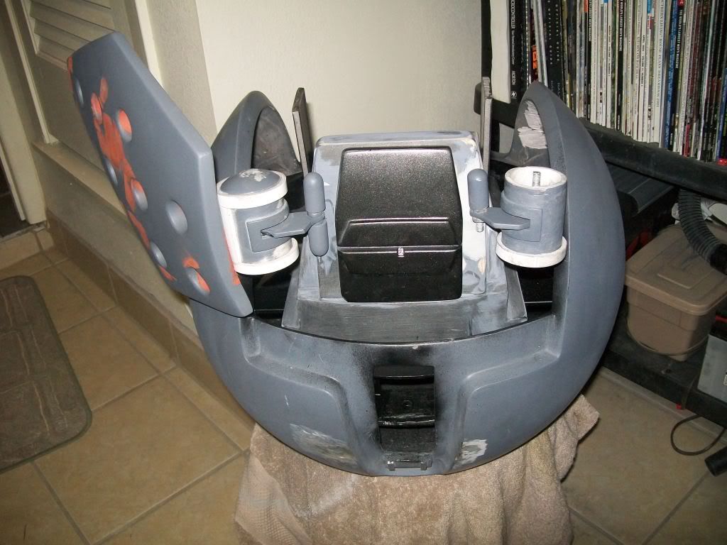
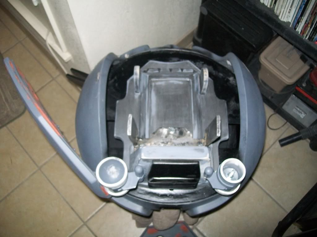
Here ya go.
-----------
I will clean some before shipping or 100% if I'm finishing them.
Thx Mathew
-
On 8/31/2010 at 7:17 AM, TK Bondservnt 2392 said:
wouldn't it be even cooler if the fans and mic were integrated along with parts that actually work?
just a thought.
=======
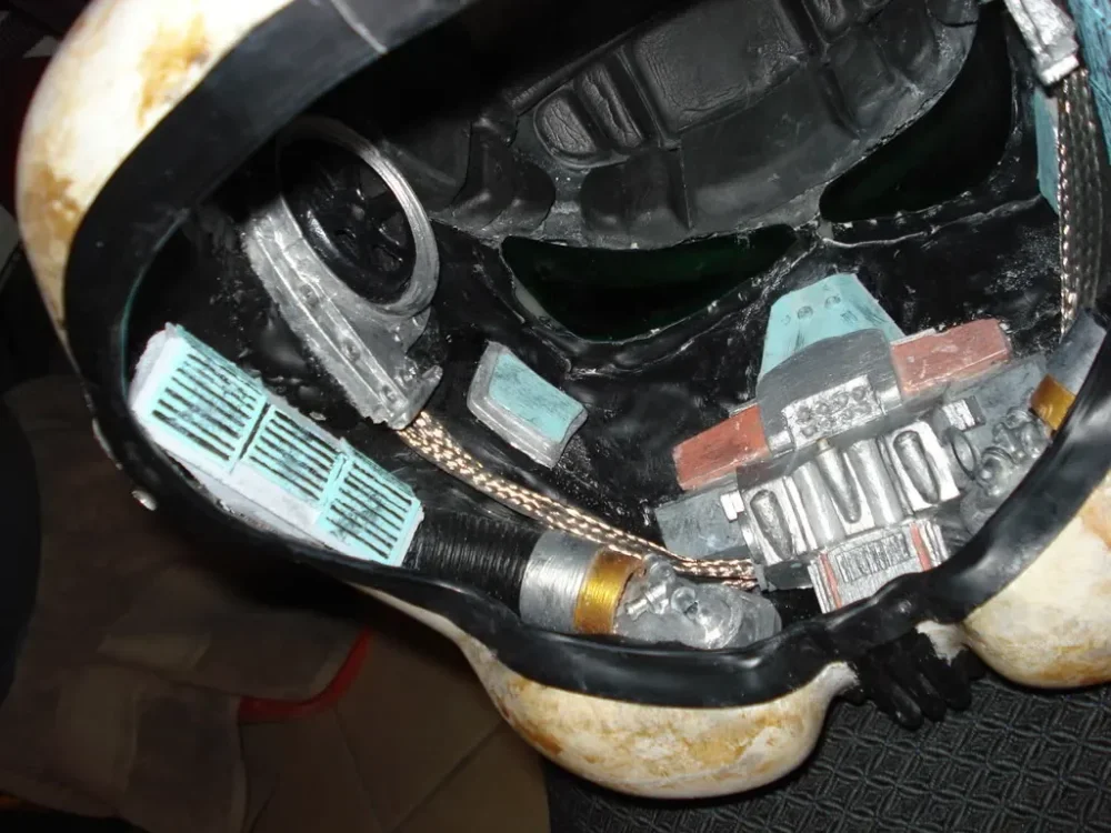
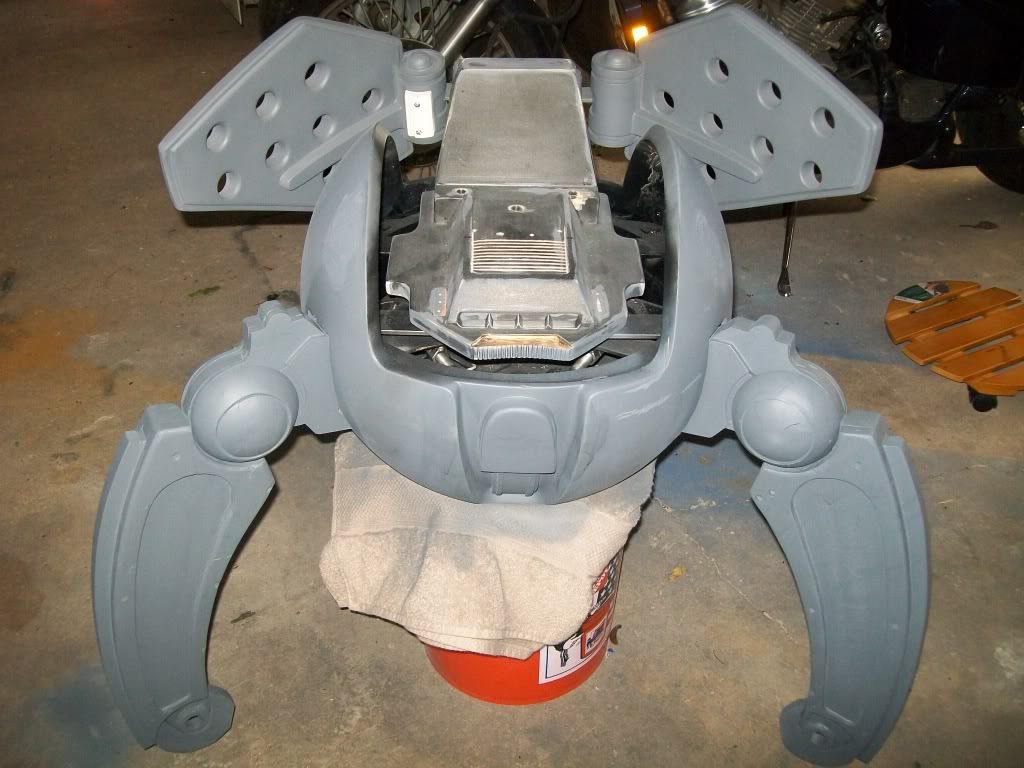
here's my guess at component locations?
red: fan intake assembly and skirting draws air in to be blown from blue area.
blue: air intake on the frown with, and exhaust at the blue on the sides. exhaust goes out the hovies along with radio broadcast.
green: broadcast speakers and air exhaust.
yellow: mic input (other sides would also dispense liquids in a stream into the mouth.
ear pads of course would be speaker enclosures.
can anyone offer more suggestions?
I think this is awesome to have a centralized design.
could you link to some images in the dictionary? I'd love to see them here...
sweet...
this looks like a great concept. fun to discuss...
You know with the stage I'm at I could potentially try, why not. I'll let you know what comes of it. Mathew
-
Troopers, these are now ready if you are still interested, just let me know how you want it, if you wanted it painted ($100) or rough (no paint-no prep $60), fiberglass add $25 ( adds weight too though ), metal cable add $15. Thx Mathew
PP is mathewsrp@hotmail.com
-
I'd like to see more on the development of this. Would it fit in any other buckets besides the TK (i.e. TS, IG or TB)?
So far guys, testing is on a 1.5"-2.0"X1.75"X1.75. The unit can get no smaller, but by changing the configuration of the unit I could custom install it in the bucket if I had it. For additional fees, of course. This will be a standardized unit for ease of manufacturing and simplicity. Testing of different designs is how we do it. Thx for asking. Mathew
-
Now that looks great.
But is it still wearable?...I've got a new MR that i'm going to fit out with the required bit's..can you still get the fans and rom fx in??
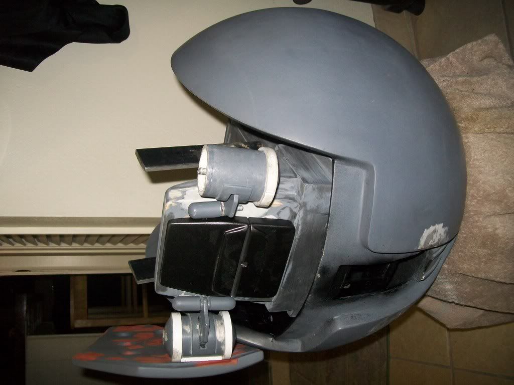
Nice padding!!
May be intouch after my holiday's
Yea I got that padding from someone on here....hmmm. Just kidding. Works and looks good though. The helmet is smaller than a tk and still fits me and I wear a 7.5 beret. Fans would need to be mounted above the lenses. Rom FX would still work if the mic was the only thing in the bucket. Thx for the questions. Mathew
-
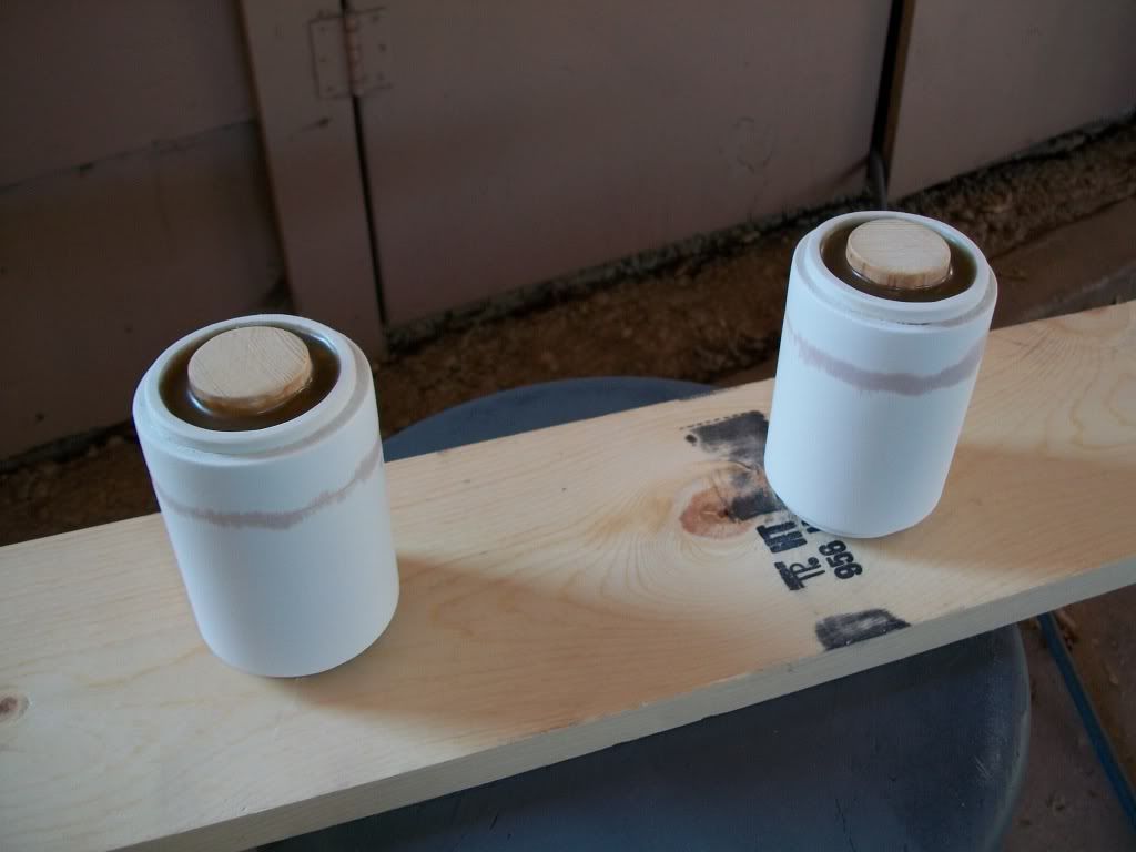
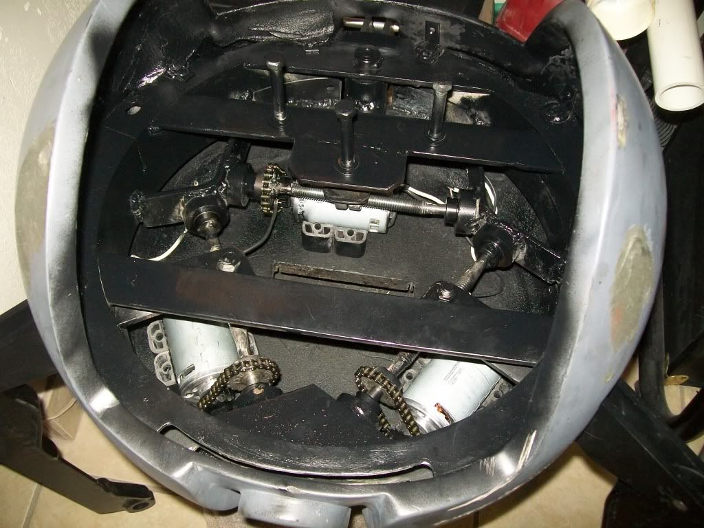
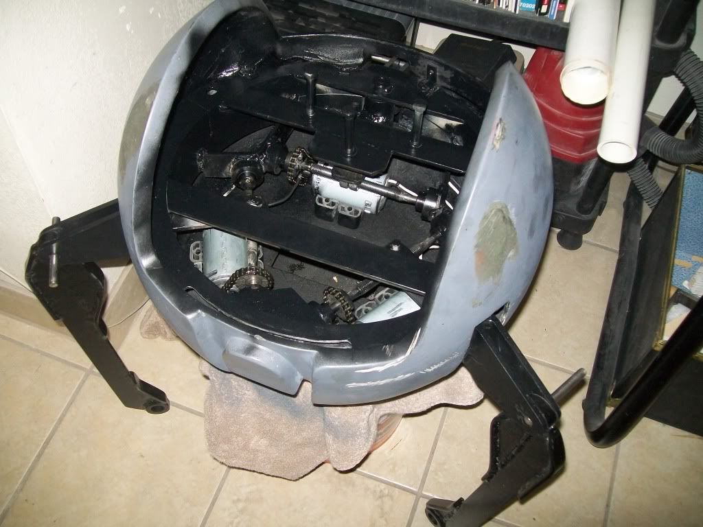
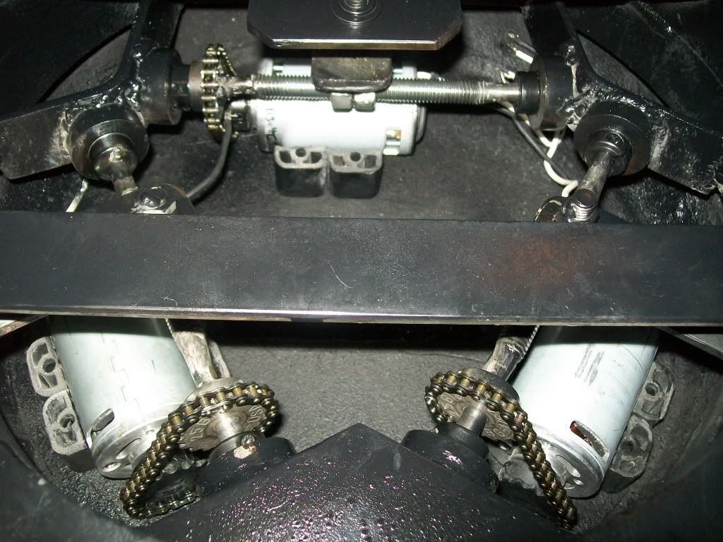
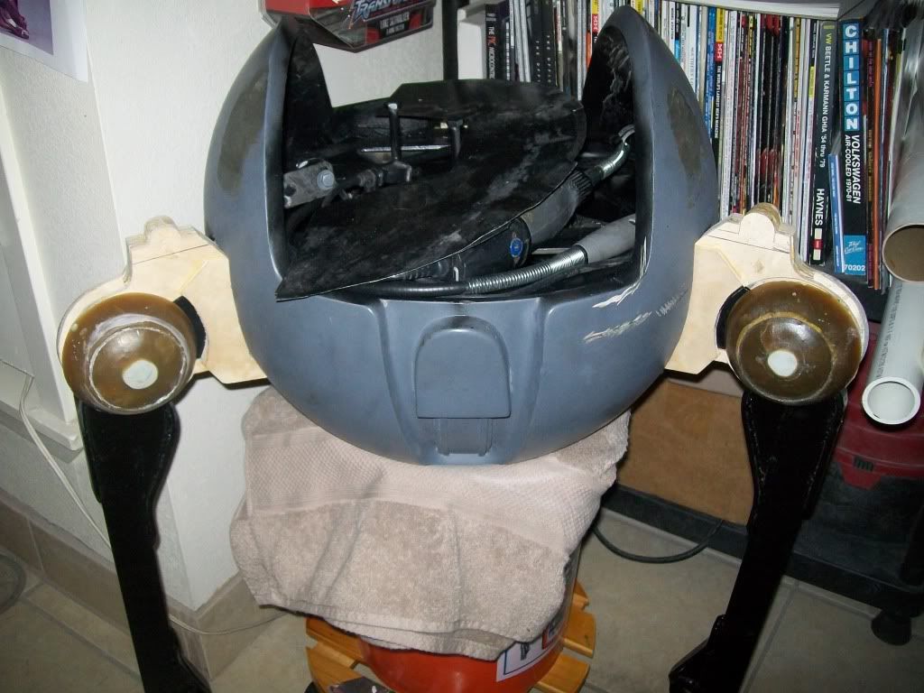
Well... lets see if any of you are interested in this.
----------
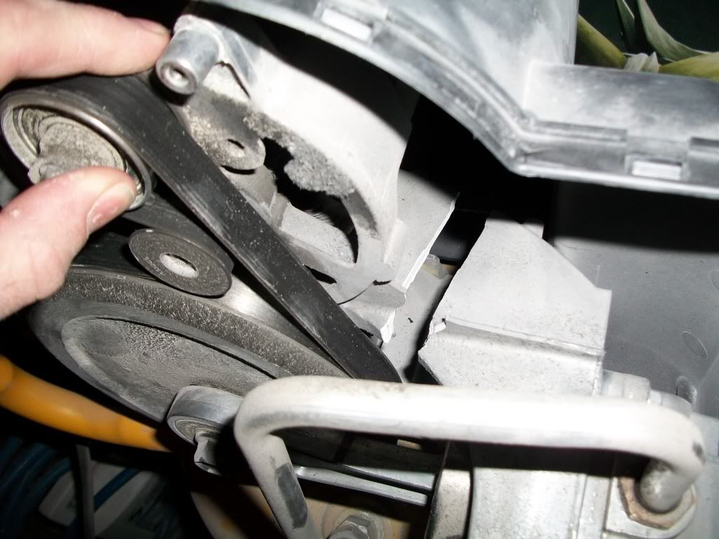
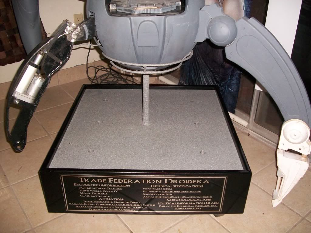
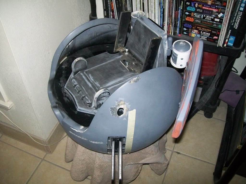
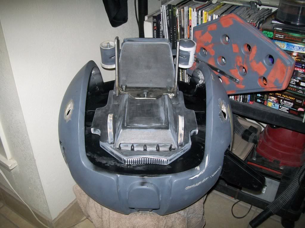
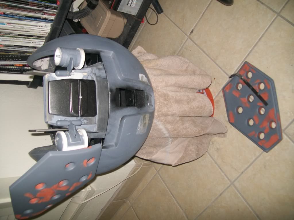
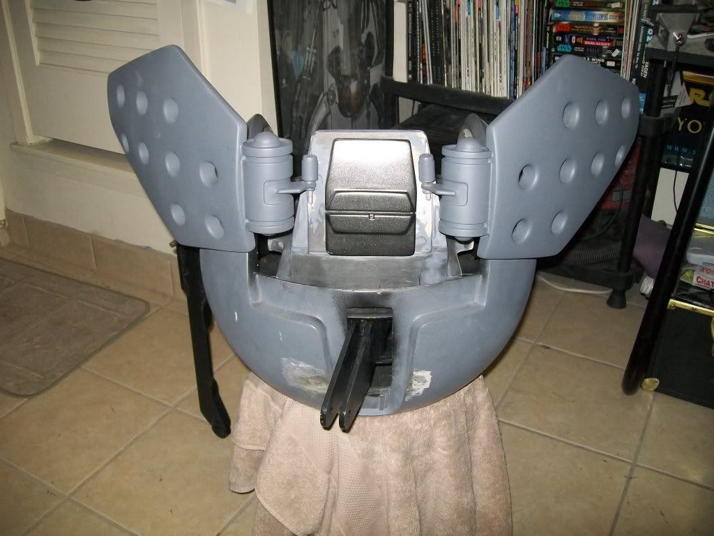
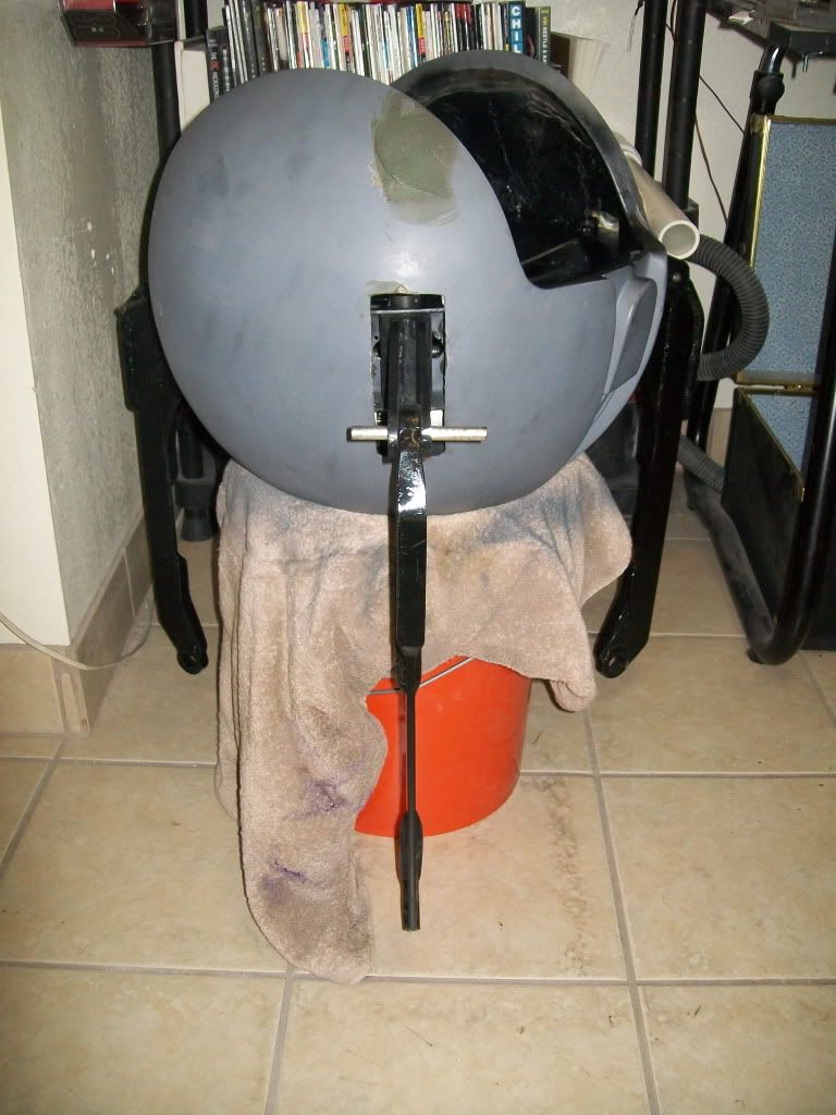
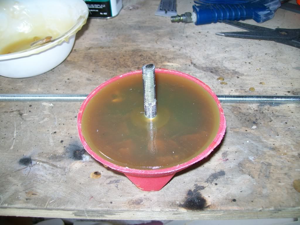
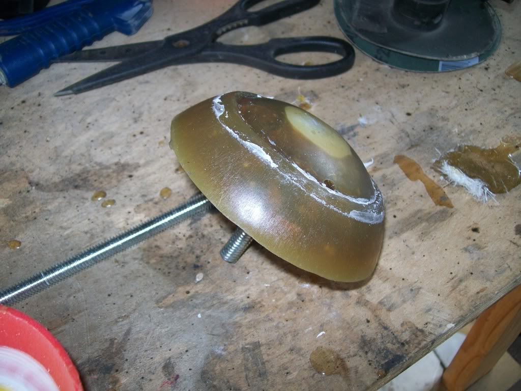
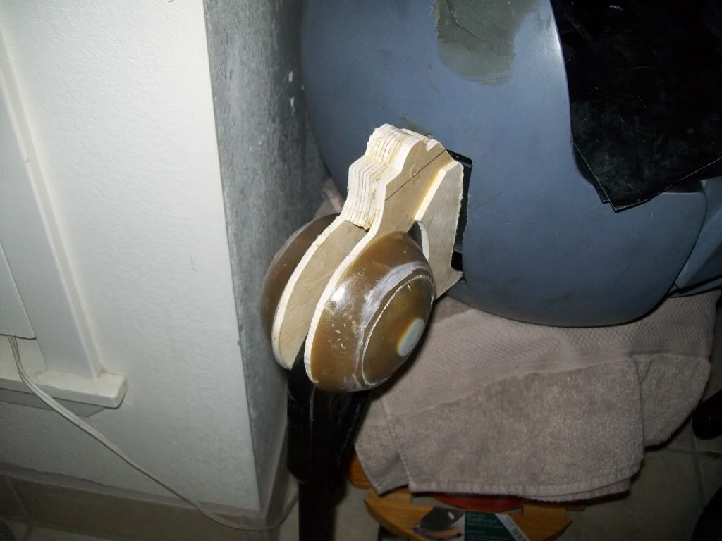
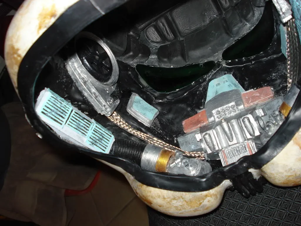
I built them just like the dictionary, check. I have this in kit form, either painted and finished for $100 or rough at $60. The metal cable is to be purchased by you. The bucket shown is my personal TD bucket. Used smooth on for the molds, and I did it in the bucket. Colors are mixed to match, so there is no set standard, just try and get it like the dict. pic. Don't worry the A/C is still in the works. Ordering has a small lag time for prep on painted orders, others will be cast roughed and shipped ASAP.
Will fit F/X to EP II Clones are the same guts(Any pics on the 1/2 scale EP II Insides?)
So for all you that always wanted your bucket to look that way here it is.
I do this for the greater empire.
Mathew
-
Sorry - I should've been more clear.
By tubes I meant the "small flexible rubber duct to hug the inside of your bucket" as per your description. The idea being that the heat exchange would happen inside the main unit mounted in the backplate, with cool air being blown up into the helment via the rubber duct snaking (which may need to be insulated to keep the air cool as it travels up the duct) up the trooper's back.
Due to the duct being a thin walled rubber without insulation any retained cooling would be eaten up before reaching the bucket, I know how it gets under the armor. To do that you would have to up the size if the unit, and that is possible, but it would cost more too. Thx Mathew
-
Will be testing performance on each unit using different Bat type and size for duration NiCd, Li, regular, and rechargables, might be nice to add a recharging plug, possible small solar flex panel carried in behind the chest plate with velcro, they are water proof too, might run about $0-50 check online, you could even mod the unit yourself, I will include where best to install the plug and socket in the wiring diagram. WB/DB with drops in temp and the most lightest and best possible efficiency with test procedure for each unit included. Rough dimension will be (LXWXH) 1.5"-2.0"X1.75"X1.75". Soon. Thx troops. Mathew
-
Eight AAs is a lot of weight. Would it be possible with this unit to mount the hardware in the armor - for instance, the backplate - and simply run a cooling tube up and into the helmet?
No tubes, this is not liquid, but you could run the power wires from your pack if your going to be in costume for a long time. You all can modify this as you like after I set it up as universal. Thx Mathew
-
It's in the re-design phase for lighter weight in the bucket. Right now It needs 8 AA to run. Haven't tested duration yet. This would come with small flexible rubber duct to hug the inside of your bucket, think of a crazy straw, but rectangular. These will have overheat auto shut off and will re-engage after cool down. Can also include a reversing switch to reverse the need for cold or hot air. It works!, but not yet. I will only have a run of 2 at this time and I will keep them up to date on the progress. When they are ready I will pm for payment to Paypal. This is an original design by me. I have been in mech. HVAC design for 13 years. If you don't mind a little weight on your bucket for that cold air, I'm working on the idea of Li batteries, but they don't last like regular batteries. These will be the most efficient I can make with the products available. You will also be able to transfer this to other buckets utilizing velcro for everything. It will come in a small kit form with ease of assembly kept simple. As far as price for heat or cold air in the bucket... What would you pay! I'm thinking about all involved just to make 2 for now. $175. Possibly shipped. Thanks for your time. If you want the list can begin, but there will be a first come basis. NO MONEY YET! I WILL LET YOU KNOW THROUGH PM!!!! Interest for now. SOON!
This is listed on other forums, I will go by who commits at what time posted. Snooze you Wait. Thx Troops.
-
Have still been on it a little at a time. No pics yet, soon though. Thanks for the continued interest. I can't wait. Still no leg movement though. It's always $ and this project comes last according to the other half
 Thank Mathew
 -
These speakers are pretty loud. These were hooked up in my aerators today with my ROM/FX Pro and they delivered a lot more volume than I expected.
I have a never ending supply of these. An upgrade is soon. Thanks for your compliment. Mathew
-
Upgraded Micro speakers are now rated at 1.5 W each and still 17mm in diameter so they will still fit inside TB, FX, Hovi, and Clone Helmet Aerators. Works great with RomFX, RomFX Pro, and many other small portable amplifiers. These are the same speakers that come inside the portable Ipod mini speaker sets. Excellent audio and sound FX reproduction capabilities. I have re-engineered these again and installed in my clone helmet with the Rom FX Pro and they work great. Turn down the sound first before testing them. Like all speakers, you can blow them. You can PM me for unit specs and pictures. I have 300 sets available and am taking orders now. Orders will now ship next day after MO or PP is received and cleared.Money Orders post to Mathew Parrott 2200 Crescent Dr Abilene Tx 79605 or Paypal accepted. $11 USD for 1 set (2 speakers) (ADD $1 USD for Credit/Debt Cards) includes shipping anywhere Can combine multiple orders Thank you and Have a great day. (PS. PP is mathewsrp@hotmail.com)
Upgraded Mini Speaker : AK-1708EA-5W
ITEM SPECIFICATIONS
1 Type Dynamic speaker
2 Dimension External diameter 17m
3 Rated Input Power 1.5 W.
4 Max. Input Power 2.0W for 1 minute.
5 Impedance 8 ohm � 15% at 2K Hz
6 Resonance Freq (Fo)900 Hz � 20% at Fo, 1V
7 Sensitivity (S.P.L.) 99dB( 1.5W/0.1m) � 3 dB at AVE 1.0K,1.2K,1.5K,2K Hz.
� 97dB( 1W/0.1m) � 3 dB
8 Frequency Range Fo � 20K Hz
9 Ttl Harm Dist Max. 10% at 1K Hz ,1.0W.
10 Voice Coil Diameter 8.5 mm
11 Magnet Rare earth permanent (Ferrite) magnet Φ8.2 x 1.2 mm
12 Weight 1.4g � 0.3g
13 Appearance Should not exist any obstacle to be harmful to normal operation; damages,
cracks, rusts and distortions, etc.
14 Operation Test Must be normal at program source 1.5W
15 Buzz, Rattle, etc. Should not be audible at 3.46V sine Wave between Fo to 20KHz
16 Polarity When positive voltage is applied to the terminal marked (+), diaphragm
should move to the front.
17 Term Stgth Capable of withstand 1kg load for 30 seconds without resulting in any damage or rejection.
18 Temperature Operating temperature: -20℃ to +60℃
Storage temperature: -30℃ to +70℃
-----------
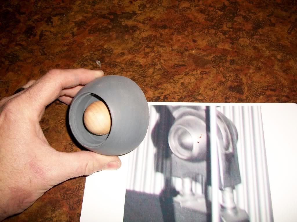
Please Note: The speaker must be installed in the aerator or equivalent sound casing (enclosure) for the maximum acoustic level to be produced, in other words volume.
Example: Cup the speaker in your hand and notice the increase in volume. All speakers have this effect. The more air tight behind the speaker, the louder the volume will become. With some experimenting, the right size enclosure will maximize the level of sound produced. There must be some sort os small area behind the speaker, like a home speaker has a speaker box. Any questions just e-mail me at mathewsrp@hotmail.com. Thank you
-
Thank you, sorry for the trouble. Mathew
Not sure, but it seems to have taken.
All I entered was:
[img=http://i301.photobucket.com/albums/nn41/Launchpad-2251/BCProto3.jpg]
-
I updated my sig and now it only shows the link to my pic? Please help. Thank you
-
So again I’m sorry for such a long time between updates. I have been busy with trying to find work, or at least making a good effort at it. This economy sucks! Which is hindering the progress of this project also. To start where I left off, the spine mold material has been purchased and the master has been finished.
I think I have more time in the spine and upper chest than any other part.
Oh, I forgot to mention that I broke another compressor!
Thank god for a Dewalt warranty! Except I am still waiting on the replacement assembly. I had to take it apart and send it to them as the closest repair place is in Ft. Worth, TX ( a 3 hour drive), so I am doing everything by hand for the last month. Should be fixed in a week or so. There’s nothing like air powered tools!
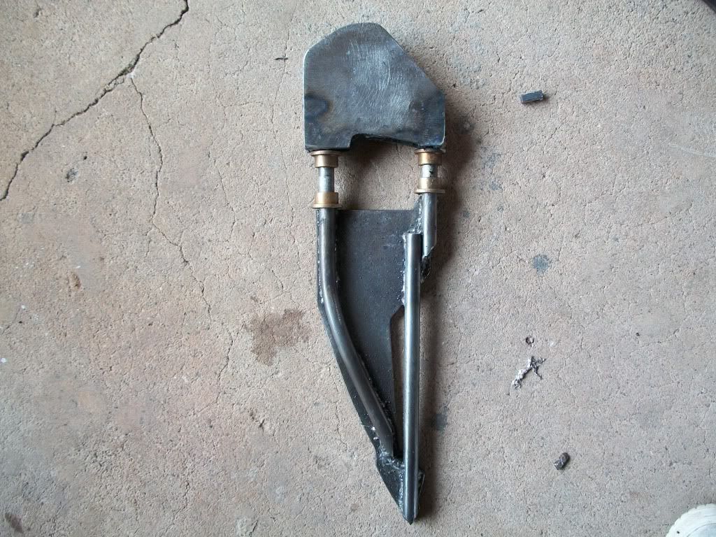
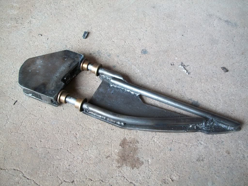
I am also set back on the initial design for the legs as the actuator will not fit in the shell that I made. It has to be correct on the outside first, they are going to make the legs look too wide, so I am back to the drawing board on the skeleton as I need the power of the actuators that are in the pics (let alone the money for them).
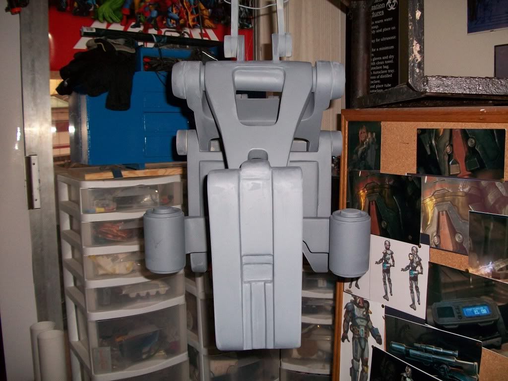
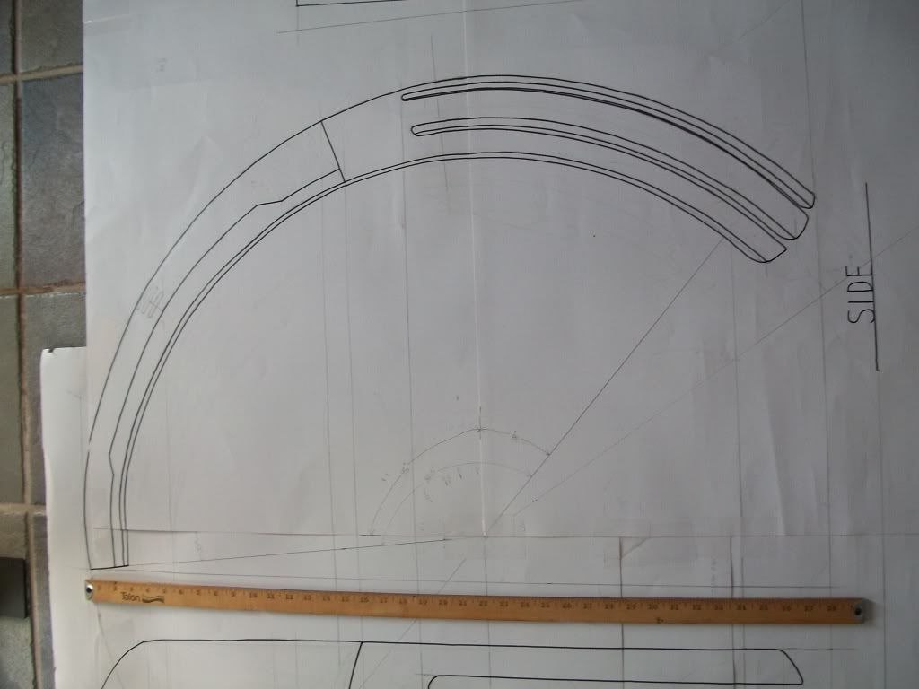
Next is the upper chest progress, note the metal ruler for size reference.
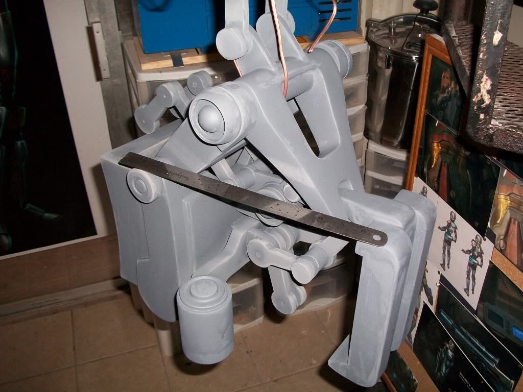
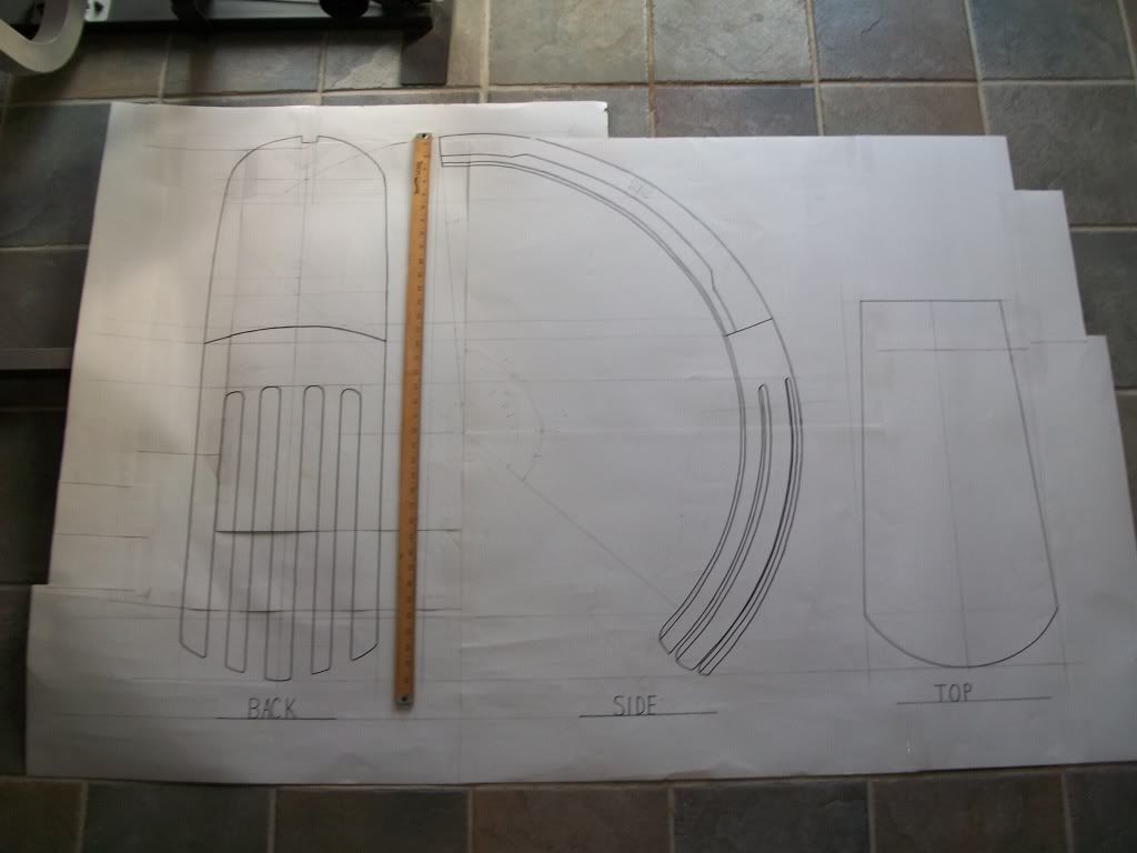
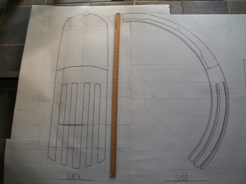
Now the prints for the back. Note again the yard stick for size reference.
Thats all for now. The next post should include a completed, very expensive, flexible spine exterior. All mold and cast material are from smooth-on. Expensive, but worth it. Oh, the mold for the feet is completed also. The empire for ever my fellow troopers!
Launchpad
-
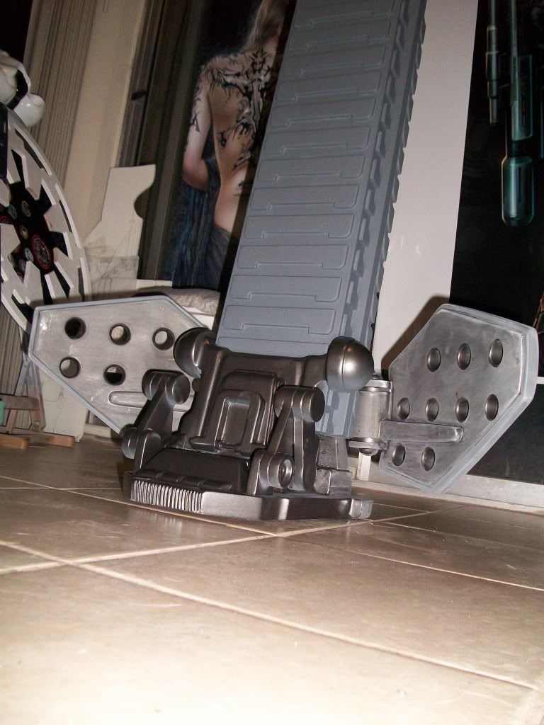
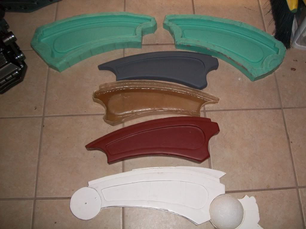
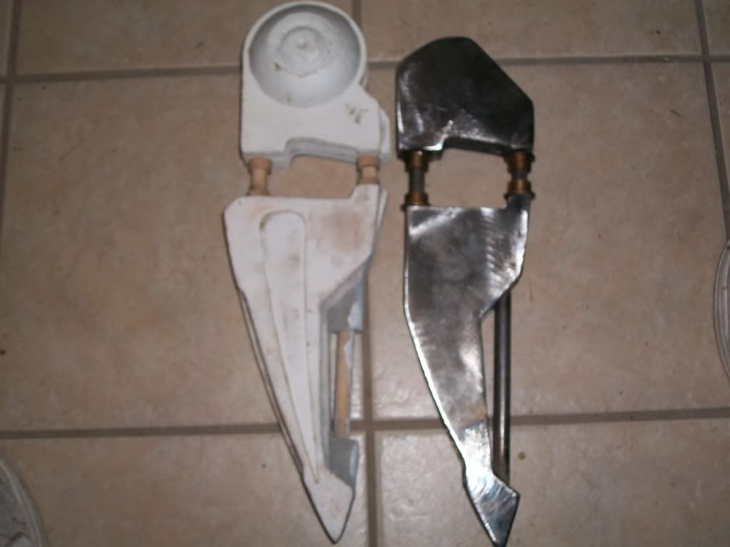
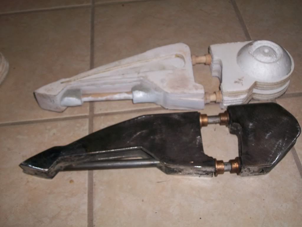
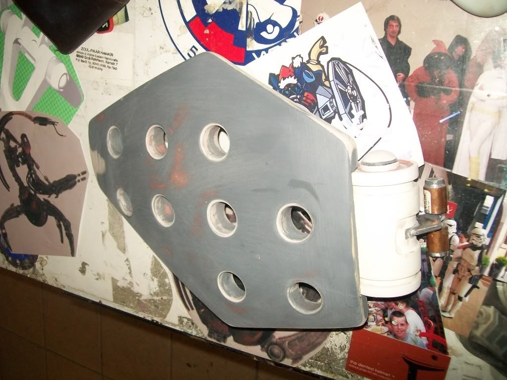
So.. It’s been a few days since I said I would post. For all of you that’s been keeping an eye on this thread, some of the pics are of the same pieces but have since been reworked. I have to admit that this is extremely nerve racking. When I go to make the following part and need to make a fit and look correct, I end up reworking the part that the new one fits into. Saying that, out of all the parts that you see, each one has been made at least 3 times each. I just want it to be right, right. Any way here are pics of the spine with remade parts and completed “private parts”. Still need to repaint the shield flaps. The other pics are of the molds for the fiberglass shells for the steel legs and I’m about to make a master set of molds for the feet. The pics show from design in foam to steel skeleton to actual shell. The mold for the spine is about to be complete also. Final step will be fitting the shells over the skeleton. More updates to come. Oh yea... the legs are starting to move. No sequence yet. I can’t wait. I would like to say that I am at 40% after only one year! I will finish this if I have to starve!!!
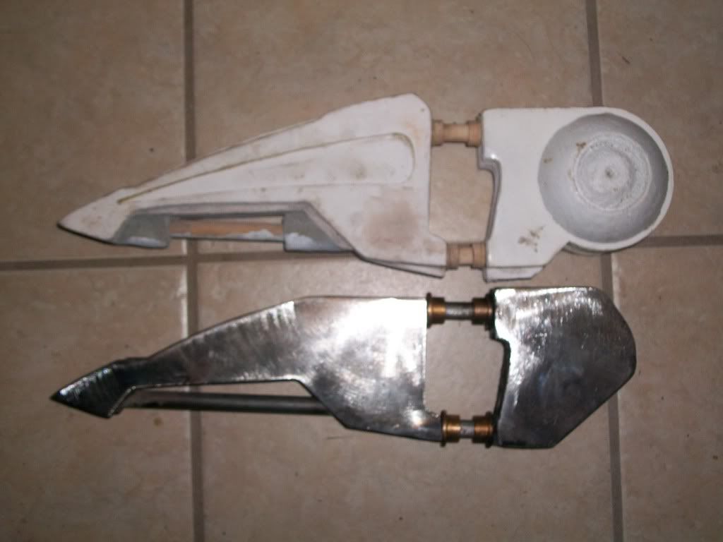
Actual
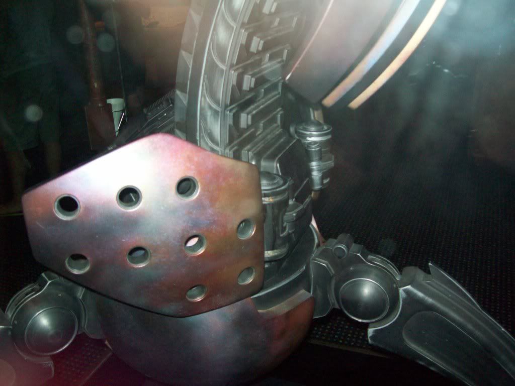
Mine
Actual
Mine
Actual
Mine
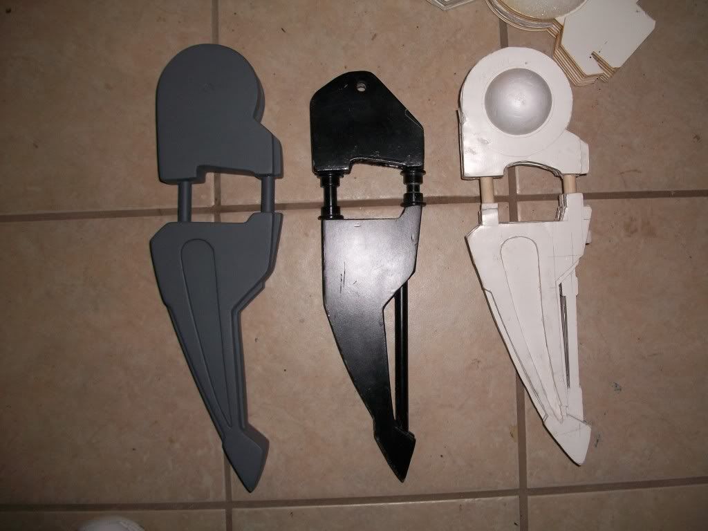
From design to mold of the main thigh...
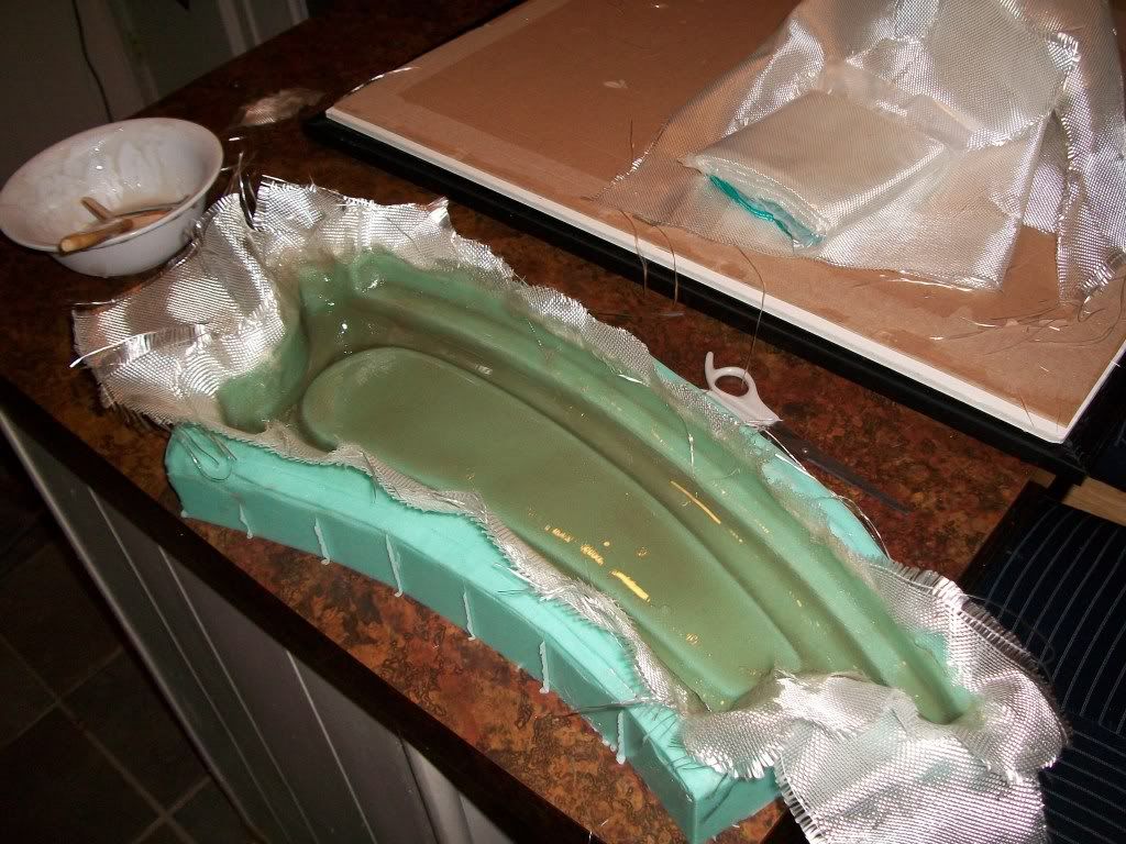
Will post more when the fitting of the shells is complete and the actual mold and shell of the spine are done!!! Yesssss!!!!!!!!! I would like to mention that one of our members in West Texas Squad poured the molds for the leg for me. Smooth on is awesome stuff!!! Thanks Dan and thanks all for you comments and support!!!!! Mathew
-
Thanks again guys. Will post this weeks progress this evening or tomorrow. Ordered the Mold material from smooth on for the spine. After the feet are done I'll start on the skeleton for the spine. I'm just as anxious as you guys! I so dedicate this thing to all of us in the legion! Empire forever!!!
-
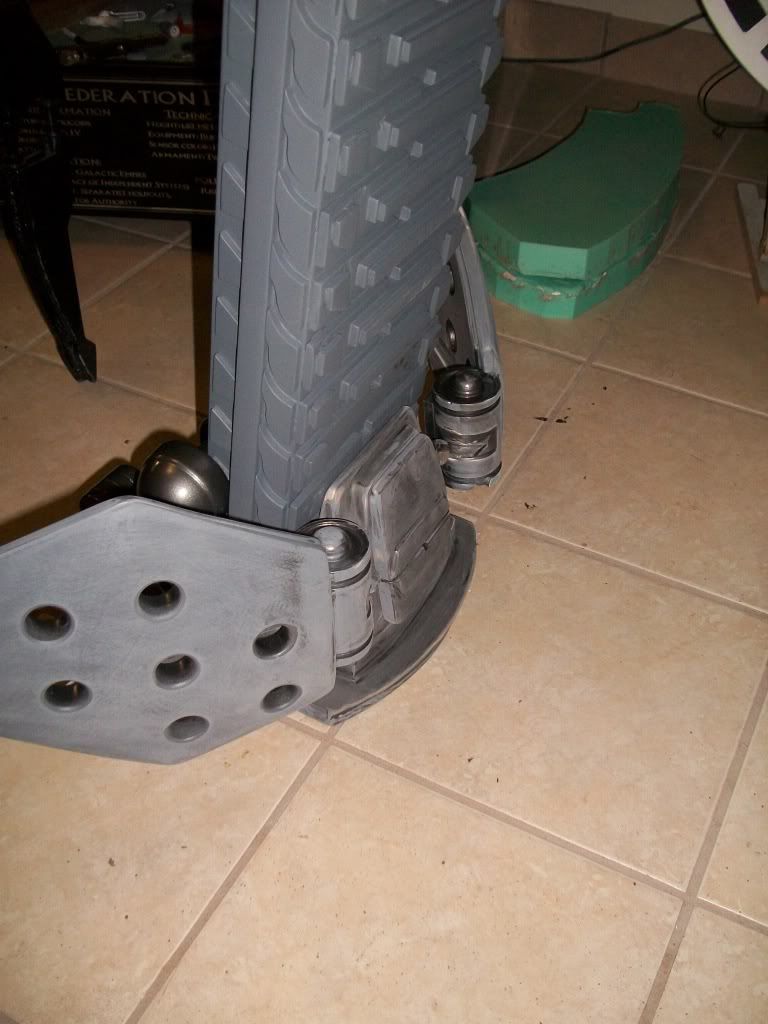
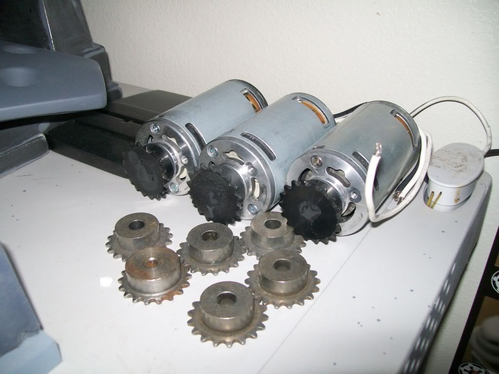
Ok all here is this months update. The wife is back from Iraq so I’ve been really busy. Spent 400 on the muscles (linear actuators) for the legs. 2 are installed and moving up and down. The third is waiting on more steel for the mods needed to install. All hips move forward and backward for taking steps. Only one leg has a foot right now due to a lack of steel around, maybe money issues too. LOL As soon as I have them somewhat synced together I’ll post a link to a you tube vid. The next step is to finish the feet for the other 2 legs, then actuators for them also. Soon, oh so very soon will I show full movement in all three legs. As it sits in its new cradle, it weighs about 95Lb. Not too bad huh?/
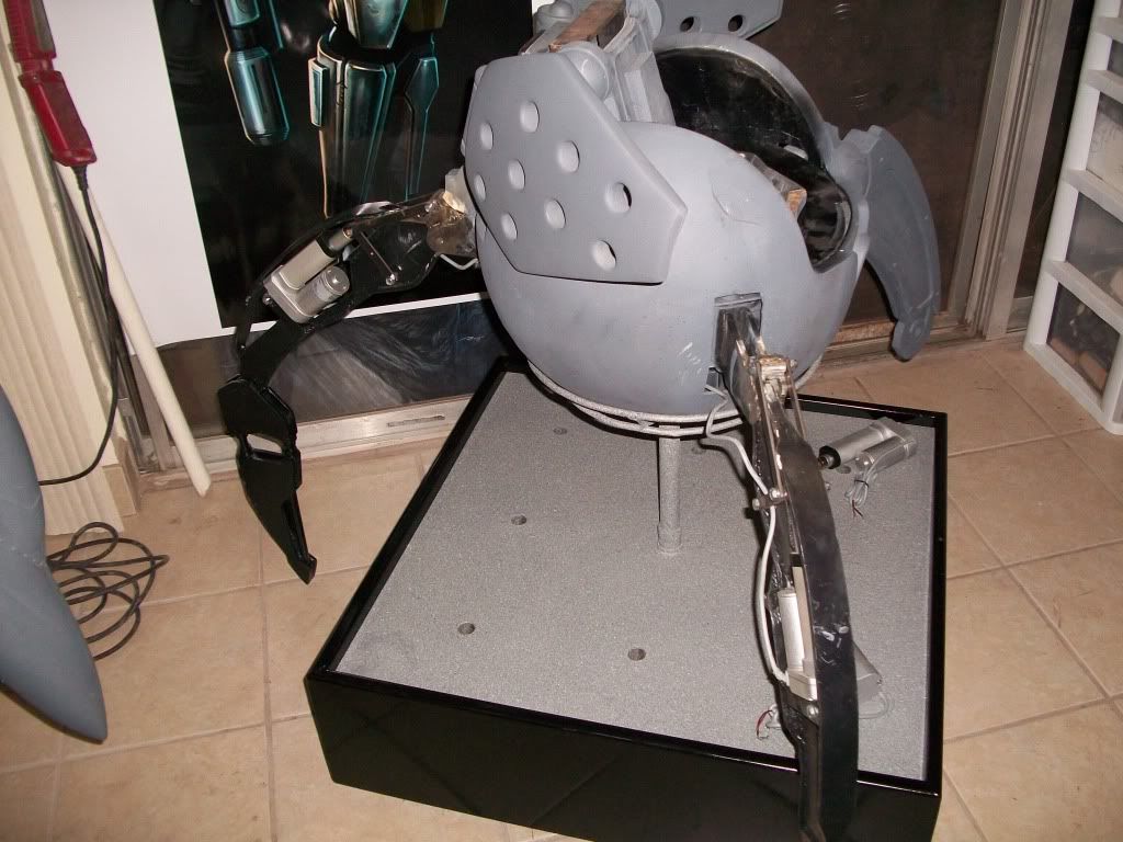
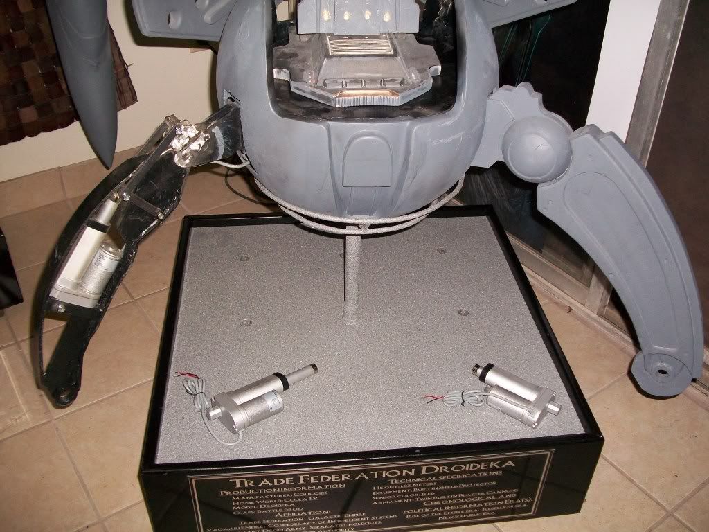

Wish me luck! Later all!! Mathew
-
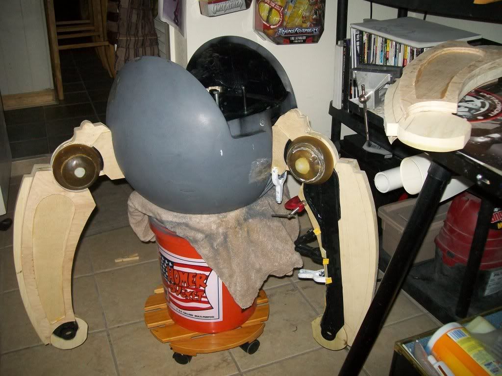
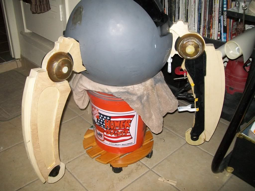
This is the other post that got missed. Kind of out of order now. Sorry.OK,all, it might not look like much more done, but believe me If I video every little thing that I have done since the last post you would all stop watching after a few minutes. The following pics are where I’m at as of this evening. After two stuck eyes, two air compressors, and tons of sand paper and grinding discs.
One pic I forgot to take is of one of the three steel toes I’ve cut out. Should start to get some excitement out of you all once I finally get one of the skeleton legs moving….Soon…MUHahAhaa. Just kidding. Now Note that one of the steel shoulders is installed. Along with the beginnings of the spine skeleton that will flex as balance is needed. Thanks for all the great comments so far. Keep em comin and I’ll keep up as long as the wife can stand it. Steel takes a whili to cut by hand no torches or nothing. Wish I had a plasma cutter or atleast a torch. Die grinder right now is my friend. Load, but my friend. The 16” disc sander comes in handy too. I’m guessing time line to leg movement within a few months at best. This is project is really my love, literally
-
Heres one of the post that got missed.
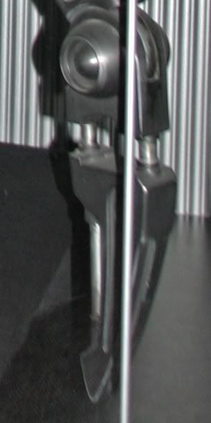
Sorry so long all for the update. The wife is deployed now and I have had the kids all summer. This is my first attempt at posting with my new Imac. Its very cool but way different than a pc, so I’m getting used to finding stuff. Here are the pics of half of the leg drives installed waiting on bolts to go through the base in the ball. Please note that all hips and legs are finished. I have started on the feet and will be attaching them next, before I can engineer the second half of the drives for the legs I need the feet complete.
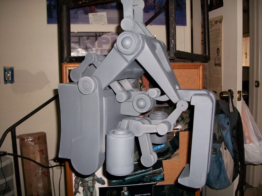
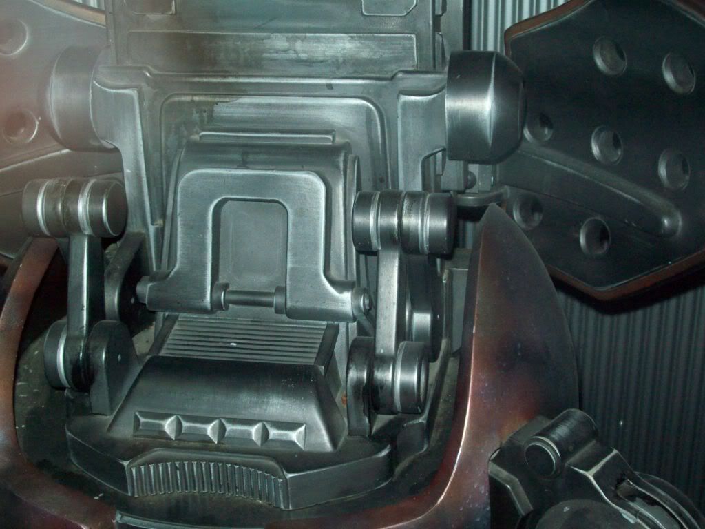
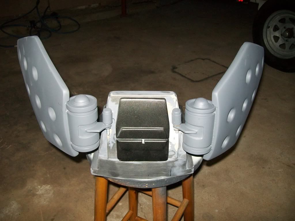
Next there are the shield generators with mounts reworked. Look at the old ones compared to these and you’ll see how much I had to do.
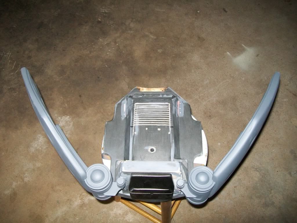
Next is a pic showing all three skeletal legs.
Thats it for now. Believe me, thats a ton since my last post. A few more burns from the torch and welder, but nothing serious. After the feet are complete I’ll be working on the molds for the legs while waiting for funds for the actuators for the legs. Thanks for the awesome comments all. This may take forever, but it will get done. Will try to post again soon. Mathew
-
guys thanks for asking. Your correct on the mold process, think car tire rubber for the spine. I have been designing a skeletal insert for bending, think of a very odd shaped bicycle chain with cables on both sides to make tight one side then loosen the opposite at the same time. This slight flex in the spine is only required for the offset of the COG (center of gravity) for when the walking is being programmed with the cpu and gyro. True movement for the offset won't be fully functional until I get the top half built. I think there are a few posts missing in between. I have since completed the gears for the Y movement of all three legs and have started working on welding the first foot. Don't know why I started this, just didn't want another R2 and as far as a 3po, I'll let Japans guys do that. Any way three legs are just as hard as 2. Programming for an extra limb. LOL Later guys. Don't forget it has to be reverse engineered. correct outside, yet still work inside. And I have to make some mods on the spine. Some of the detailing is incorrect. About 35 of the pieces. Yuk
-
Here’s this few weeks worth of work. The final molds on the legs are waiting on the linear actuators before completion, but the shoulders and skins are starting to take shape. I’ve been working on the feet some, but not much more to show here but this is where I’m at as of now. Starting to look like one now. Huh? Later Mathew
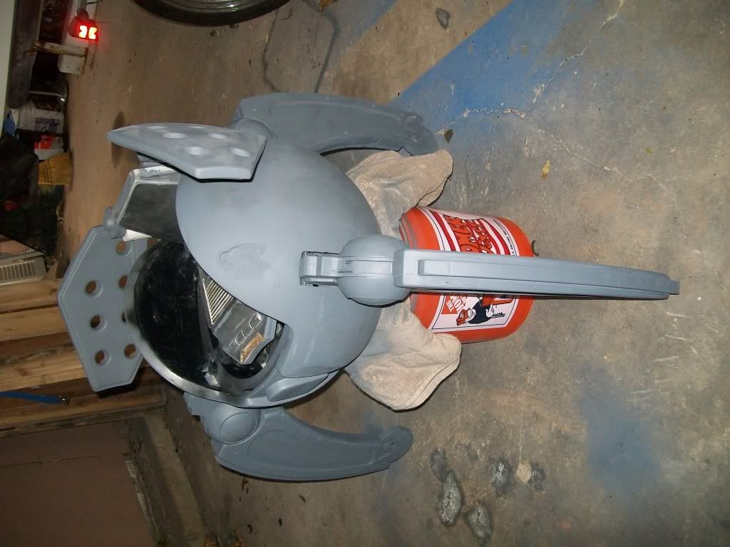
More to follow later.
-
All current orders as of today were shipped this morning. Thanks everyone!!!
Fake electronics GUTS FOR YOUR BUCKET
in Electronics for Helmets / Blasters
Posted · Edited by gmrhodes13
link removed no longer working
This is the pic from the dictionary.