My solution to the 24-hour problem
(sorry for translator errors)
Necessary:
Drill, 4mm drill bit
Soldering iron
Hot Glue Gun
Screwdriver
Knife
Tweezers
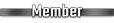
Microswitch
Thin wire
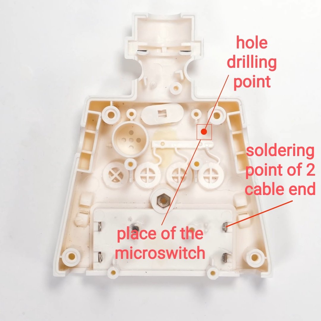
I desoldered my microswitch from a computer mouse. I forgot to measure it, but I think it had dimensions of 8x8mm and the button head itself had a diameter of 3mm. It should fit in the indicated place.
Next steps
1. Unscrew the battery cover, remove the batteries
2. Disassemble the head (you have to pull very hard), neck cover, front panel, screen panel, arms, legs, handle and button mechanism.
This video may help: https://youtu.be/o8DqA4FCs2Y
3. Unscrew the alarm button electronic board and remove the button.
4. Unscrew the screen backlight button (head) electronic board.
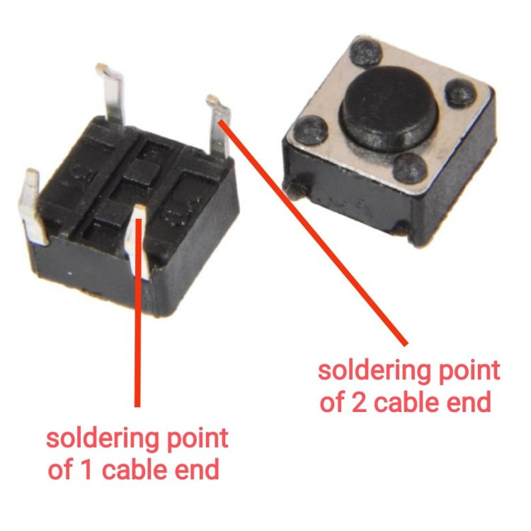
5. In the place indicated in the photo, drill a hole with a diameter large enough to fit the head of the microswitch button (in my case the hole diameter was 4 mm). To mark the drilling location, I painted the microswitch button with paint (you can use e.g. lipstick) and pressed it with tweezers in the selected place to make a mark.
6. Cut two pieces of wire, approximately 10 cm long.
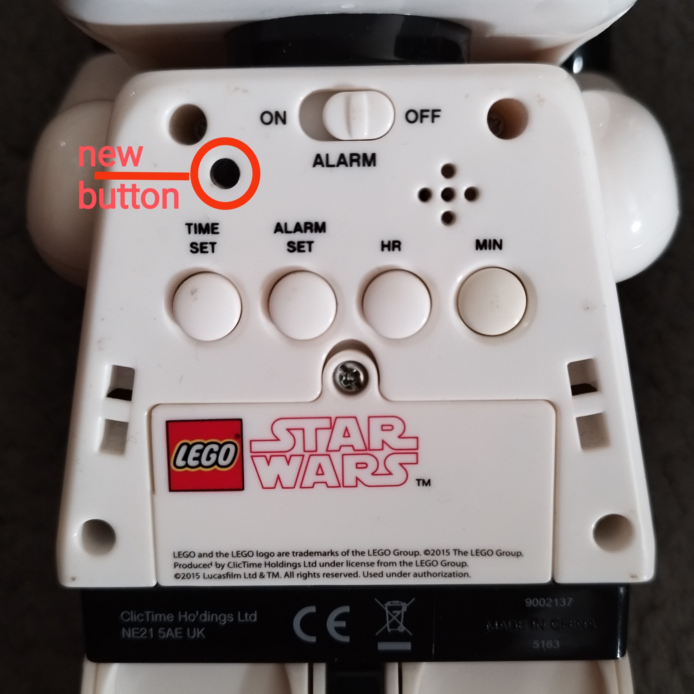
7. Solder one end of wire No. 1 to the microswitch, and the other end to point I5 (indicated in the photo) - insert the wire from the screen side, but solder it from the other side.
8. Solder one end of wire no. 2 to the microswitch and the other end to the battery contactor pin (indicated in the photo), i.e. the power point (3V+). The red wire is already soldered there, just solder wire no. 2 to it
9. Arrange the wires appropriately, place the button in the hole and cover it with hot glue, but be careful not to block the excess glue in the place for the alarm off button. While gluing, it is a good idea to hold the microswitch, e.g. with a toothpick.
10. Install the handle and button mechanism, legs, arms, and screen panel.
11. Insert the alarm button and screw on the alarm button electronic board
12. Screw on the screen backlight button (head) electronic board.
13. Insert the batteries and CHECK IF THE NEW 24H BUTTON works properly!
14. Install the front panel, neck cover, head.
15. DONE!