

FISD E-11 Reference Team
-
Posts
53 -
Joined
-
Last visited
Content Type
Profiles
Forums
Gallery
Articles
Media Demo
Posts posted by FISD E-11 Reference Team
-
-
1 hour ago, imperialbrewer said:
Could we get an updated link to the PDF document Photo Compendium? That Google Drive link is no longer working. Thank you!!
The links to the PDF files are available in three different postings and this specific document was updated in only two of them. Thank you for highlighting this.

Found and fixed that broken link.
-
 2
2
-
-
The FISD E-11 Reference Team would like to take this opportunity to thank Jesse (dracotrooper) for submitting a new modification for the magazine well.
The new content has been added to chapter #15 (see Mod G). Thank you very much for contributing information to this reference.
Also both PDFs (A4 and US letter size) have been updated.
-
4
-
-
As many of you will already know, chapter #32 - Downloads contains two PDFs (A4 and US letter size) that are direct copies of this thread content, with only minimum changes to optimize some page breaks here and there. Both PDFs have now been updated with all the additions from the contributors and the links are now also available in the very first posting. A document version (currently Dec. 2017) is stated on page 2 of each PDF.
-
2
-
-
The FISD E-11 Reference Team would like to take this opportunity to thank Jesse (dracotrooper) for submitting a PDF document with photos from Aaron's cleaned Sterling parts set.
The link has been added to the existing PDFs. Thank you very much for contributing information to this reference.
-
1
-
-
Fixed all links that broke since the last forum upgrade. If you still find a broken link, please send a PM. Thank you.
-
Just recently, most of our photo links broke and we are currently working to bring back all the content.
This might take a while and to provide an interim solution, please check chapter #32 (Downloads).
There you'll find a printable PDF with most of the information from the thread.
We will update you again, when the issue has been fixed. Sorry for any inconveniences.
-
2
-
-
On 27.1.2016 at 1:20 AM, Tr00per said:
(Video)
Thanks Dennis, we had found (and integrated) that video while checking the other clip, that you brought to our attention.
Both videos (and other useful information) can be found in chapter #33 (Gallery).
-
1
-
-
The FISD E-11 Reference Team would like to take this opportunity to thank Chris (Thrawn's guard) for submitting photos from several modifications like the magnetic magazine connection, the bottom side of the counter socket, another metal part in the grip and of course his amazing scope.
You have been added to the friends list of this team-account, so everybody viewing this profile will see, you have contributed information to this reference. Thank you very much.
-
2
-
-
The FISD E-11 Reference Team would like to take this opportunity to thank Steve (gazmosis) for submitting photos from his selfmade counter window in D-shape.
You have been added to the friends list of this team-account, so everybody viewing this profile will see, you have contributed information to this reference. Thank you very much.
-
1
-
-
The FISD E-11 Reference Team would like to take this opportunity to thank Mike (Twnbrother) for submitting photos from the front sight pin (made from a threaded rod) and the movable magazine release button.
You have been added to the friends list of this team-account, so everybody viewing this profile will see, you have contributed information to this reference. Thank you very much.
-
3
-
-
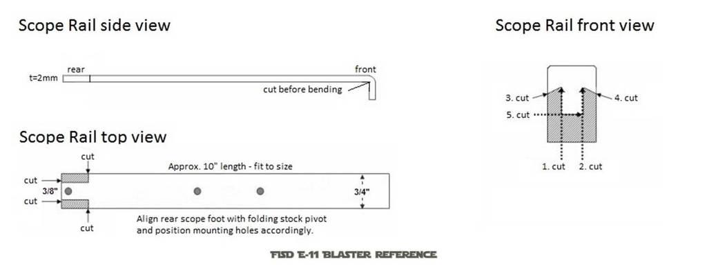
The FISD E-11 Reference Team would like to take this opportunity to thank Germain (The5thHorseman), Christian (Novak Dimon) and Stefan (Turrican) for submitting content regarding the scope rail.
You have been added to the friends list of this team-account, so everybody viewing this profile will see, you have contributed information to this reference. Thank you very much.
-
3
-
-
The FISD E-11 Reference Team would like to take this opportunity to thank Vern (TK Bondservnt 2392) and Dennis (TK-50101 Blue Snaggletooth) for submitting photos from original Hengstler counters,
and Dennis (Tr00per) for bringing the Sterling disassembly video to our attention.
You have been added to the friends list of this team-account, so everybody viewing this profile will see, you have contributed information to this reference. Thank you very much.
The new content can now be found in chapter #33 Gallery.
-
3
-
-
#33 - Gallery
This chapter provides more visual information on individual parts of the E-11 blaster.
Sterling L2A3 Mk4 9mm:
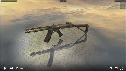 - with permission from youtube member "Gun Disassembly"
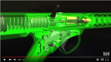 - with permission from youtube member "Noble Empire"
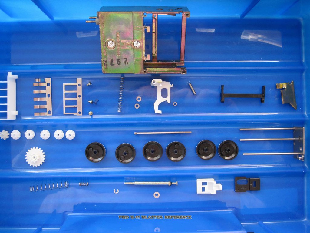
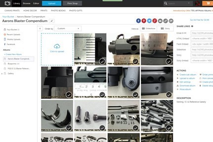 - a link to many photos of a precisely cleaned Sterling parts set.
Sterling parts in downloadable PDF document Photo Compendium
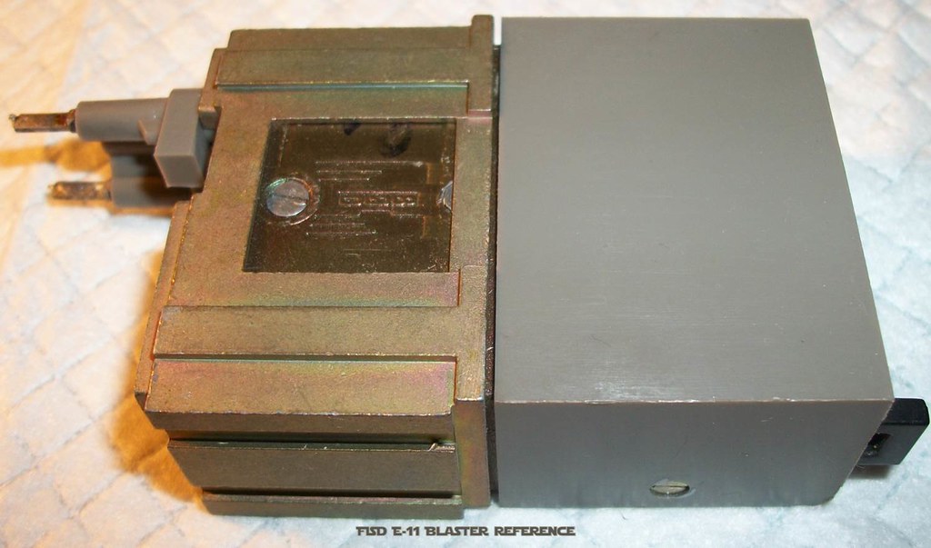
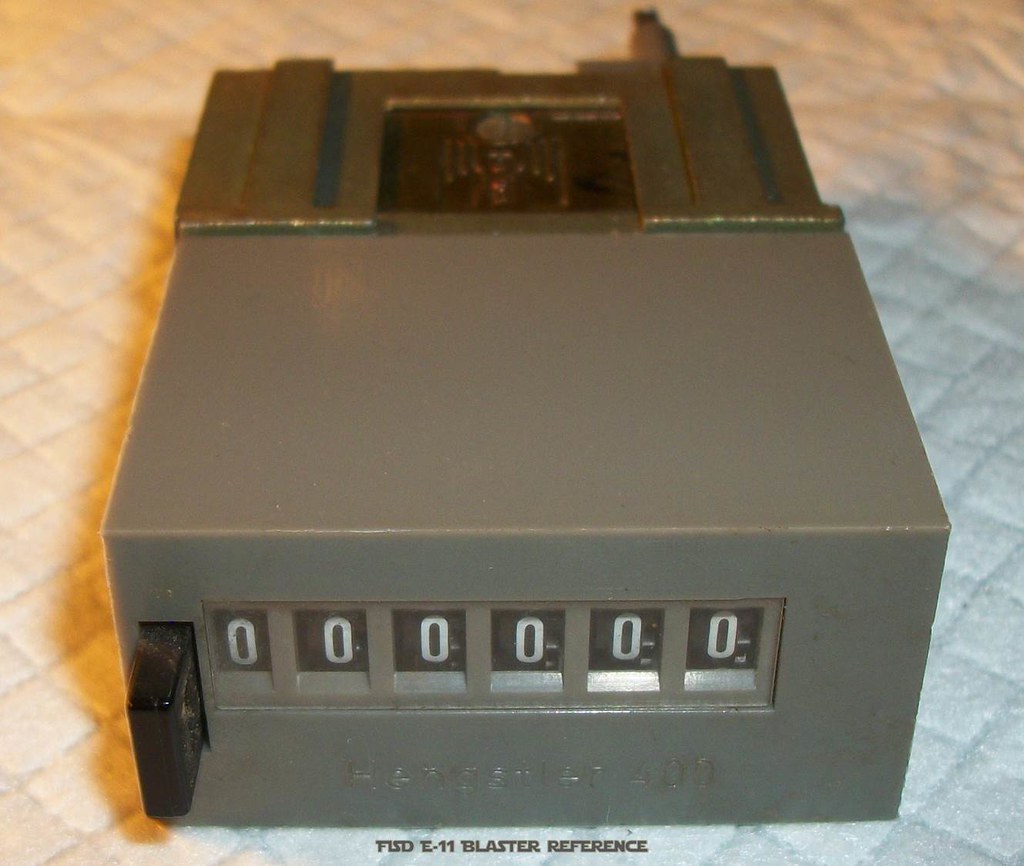
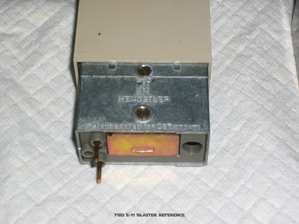
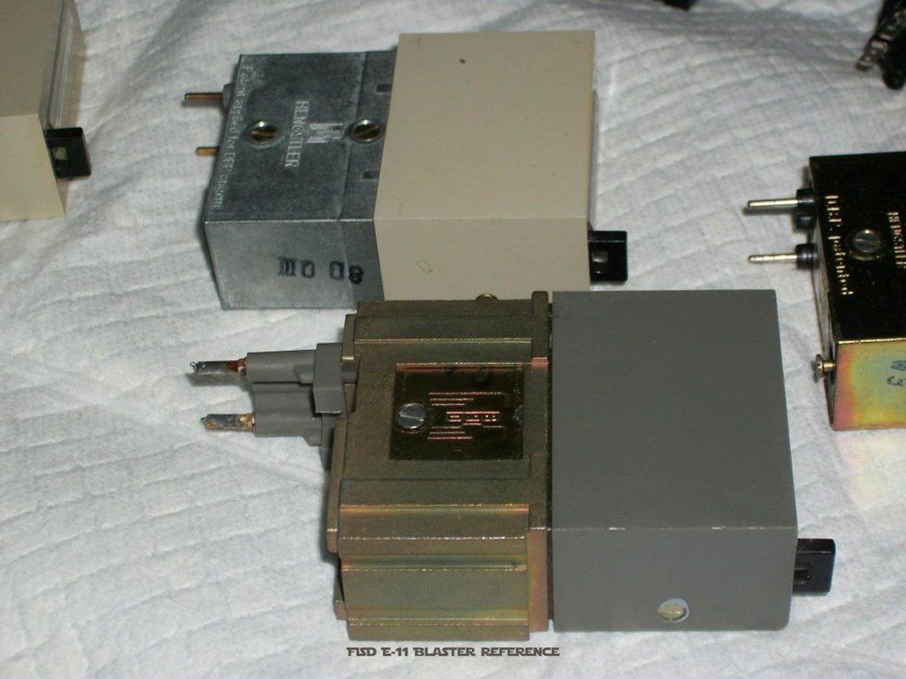
Hengstler Counter Variations:
From Dennis (TK-50101 Blue Snaggletooth):
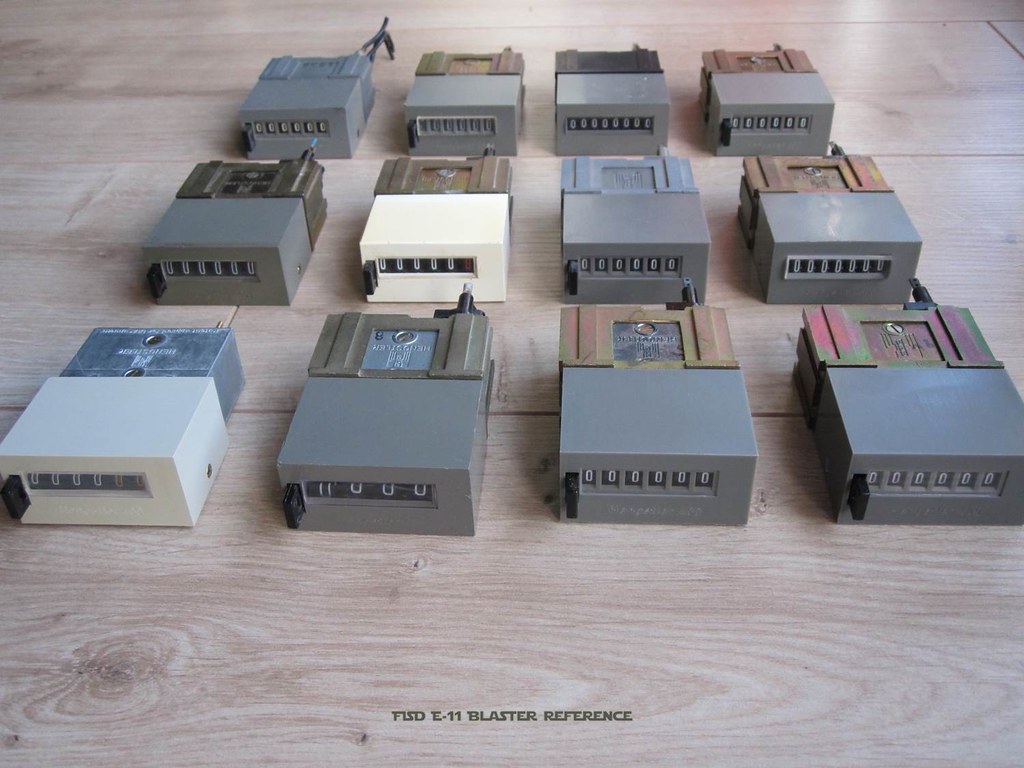
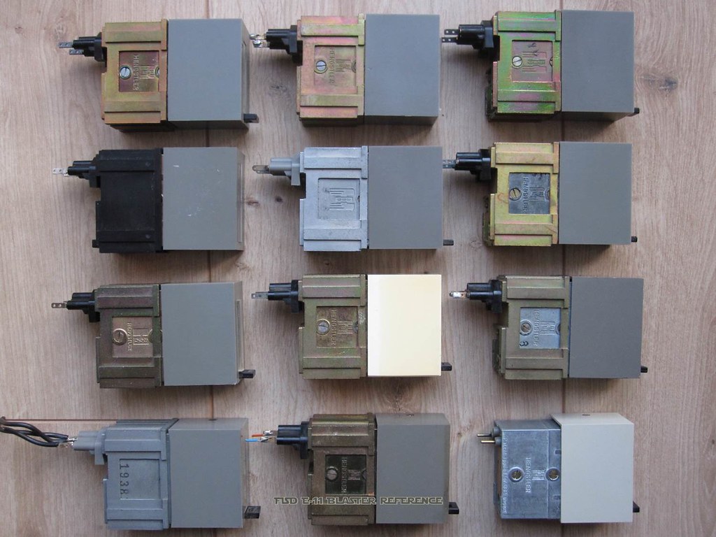
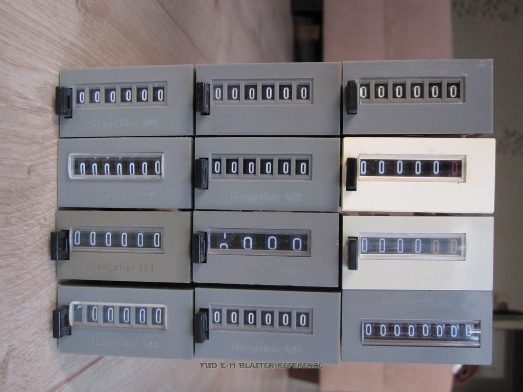
From Vern (TK Bondservnt 2392)
-
Important request to everybody, who wants to add content to this reference:
We ask you to please not add this in a new post. Instead of that, just contact us via PM.
This is mandatory to avoid any copyright issues or getting defect links in the future. The last thing we would want, is to get in trouble because of that.
Also please bear in mind, there is not a single person answering your PM, but a team of people, living in different time zones.
Because of that, it will take a while to discuss and agree on things, but you can be sure your PM is being worked.
-
On 8.8.2015 at 2:48 AM, TK Bondservnt 2392 said:
Photos shown above can all be added to the reference.
I own these. Shot personally.
crop and tag with team logo. with credit tag line To Vern Beezer.
discard or add as you wish.
(...)
Vern, thank you very much for your photos from the original parts. We will soon create a new chapter, where some of these can be included.
Your pictures will then get the common watermark and (once uploaded to this reference) you will be stated publicly as a content contributor in a new post, with a direct link to this update.
For any additional discussions (or in case, this is not what you had in mind) please let's continue to use our existing PM conversation. Thank you very much.
-
1
-
-
Update notification:
Chapter #30 (Blueprints)
just got enhanced with a link to a photo collection of a precisely cleaned Sterling parts set.Edit: this parts set has been moved to Chapter #33 (Gallery)
-
1
-
-
Update notification:
Chapter #32 (Downloads) has just been added to provide all content in downloadable PDF (DIN-A4 and US letter).
-
4
-
-
Epilogue
This reference is the result of months of work taking place behind the scenes, through extensive collaboration online. The intent is not to serve as a "HOWTO" for a resin E-11 build, but to serve as inspiration for those who would like to take on the challenges of modifying their builds in some small way, or many small ways.
Should you have questions about anything you see here, don't hesitate to ask one of the members of the team. This reference is a living document, and who knows what may be added to it in the future. Perhaps one of you reading this will one day come up with a modification that has not been thought of yet and it will change how Troopers and Cadets build their E-11s forever. If you do, don't be surprised if you're asked for some assistance in bringing that modification to the reference for sharing with the community here.
So, there it is. For now, we will leave it here, as is, in the vein of Troopers (and in some cases, Cadets) Helping Troopers. We all hope it serves to help a great many of you in leading the next wave of E-11 builds into a new level of fun and realism, and thank so many of you who came before us for inspiring each of us in so many ways.
Thank you for reading and be sure to share this information with anyone who can use it.
With Unquestioned Loyalty.
- The Members of the E-11 Reference Team
-
6
-
-
#32 - Downloads
Full content as downloadable PDF document in DIN-A4 size
Full content as downloadable PDF document in US letter size
Sterling parts in downloadable PDF document Photo Compendium
The PDFs are direct copies of this thread content, with only minimum changes to optimize some page breaks here and there.
If you find any other substantive differences, please send a PM.
Think before printing - please consider your responsibility to the environment before printing a PDF. Thank you.
-
5
-
-
#31 - Measurements
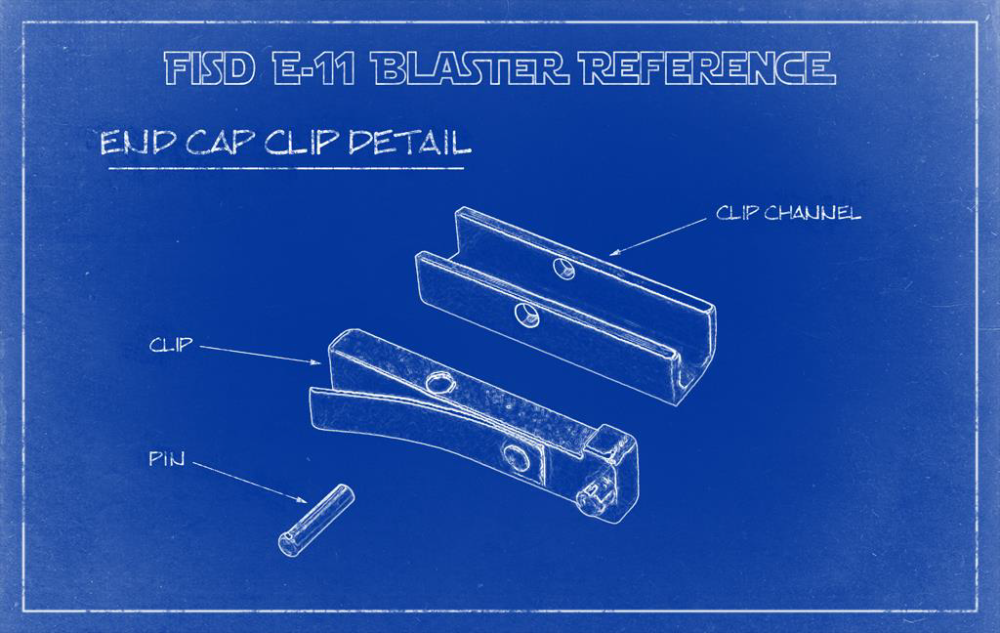
End Cap Clip:
Clip length: 1.463" (37.160mm)
Clip width: 0.258" (6.553mm)
Clip T-head length: 0.174" (4.420mm)
Clip T-head width: 0.375" (9.525mm)
Clip overall thickness/height: 0.178" (4.521mm)
Diamond knurling length (120deg cross): 0.355" (9.017mm)
Locking pin bottom diameter: 0.123" (3.124mm)
Locking pin length below flush 0.110" (2.794mm)
Locking pin top diameter: 0.090" (2.286mm)
Locking pin head above flush: 0.032" (0.813mm)
Locking pin CENTER from T-end: 0.084" (2.134mm)
Spring rivet diameter: 0.104" (2.642mm)
Spring pin head above flush: 0.024" (0.610mm)
Spring length: 1.075" (27.305mm)
Spring width: 0.231" (5.867mm)
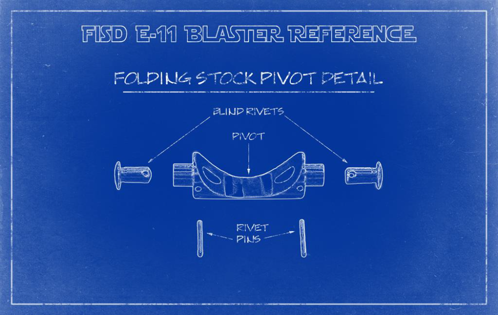
Pivot pin diameter: 0.096" (2.438mm)
Pivot pin length: 0.376" (9.550mm)
Pivot hole CENTER (from knurled end): 0.540" (13.716mm)
Channel length: 1.285" (32.639mm)
Channel width (outside): 0.380" (9.652mm)
Channel width (inside): 0.259" (6.579mm)
Channel height: 0.325" (8.255mm)
Channel hole CENTER (from knurled end): 0.565" (14.351mm)
Muzzle screws:
Head Diameter: 0.368" (9.347mm)
Head Height: 0.252" (6.401mm)
Thread diameter: 0.245" (6.223mm)
Thread Length: 0.643" (16.332mm)
Overall Length: 0.895" (22.733mm)
Hex wrench size: 3/16"
Grip screw:
Head Diameter: 0.366" (9.296mm)
Head Height: 0.252" (6.401mm)
Thread diameter: 0.246" (6.248mm)
Thread Length: 1.273" (32.334mm)
Threaded Area: 1.073" (27.254mm)
Unthreaded Area: 0.200" (5.080mm)
Unthreaded Diameter: 0.250" (6.350mm)
Overall Length: 1.525" (38.735mm)
Hex wrench size: 3/16"
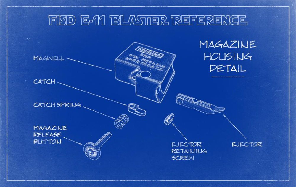
Ejector Retaining Screw:
1/4" X 28 TPI
Hex wrench size: 1/8"
Overall diameter: 0.247" (6.274mm)
Threaded length: 0.382" (9.703mm)
Overall length: 0.508" (12.903mm)
Closest metric size: M6 X 0.75 pitch X 10mm
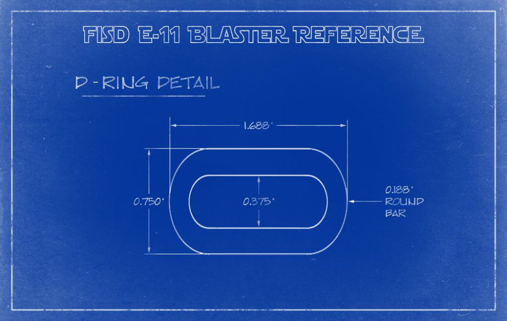
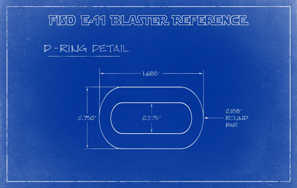
D-Ring:
Overall width: 1.688" (42.875mm)
Overall height: 0.750" (19.050mm)
Round bar thickness: 0.188" (4.775mm)
Bends inside diameter: 0.375" (9.525mm)
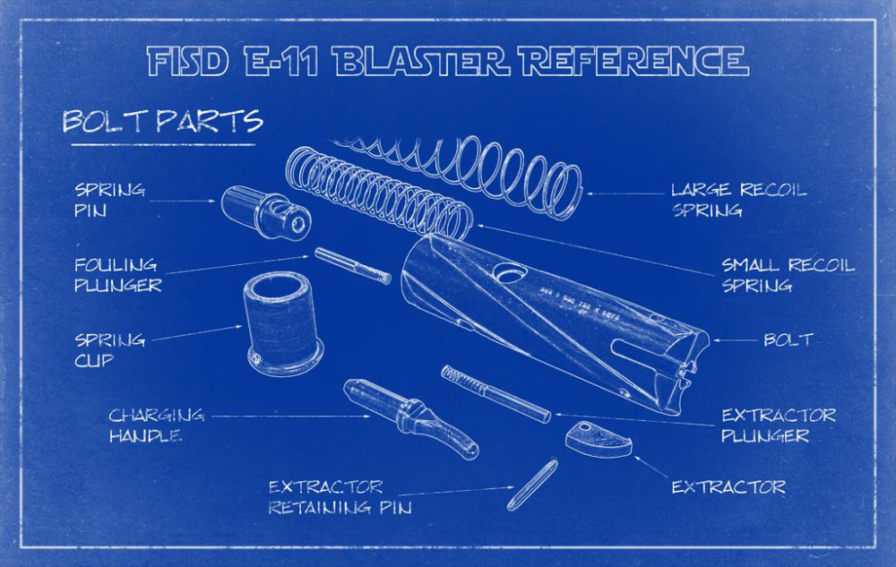
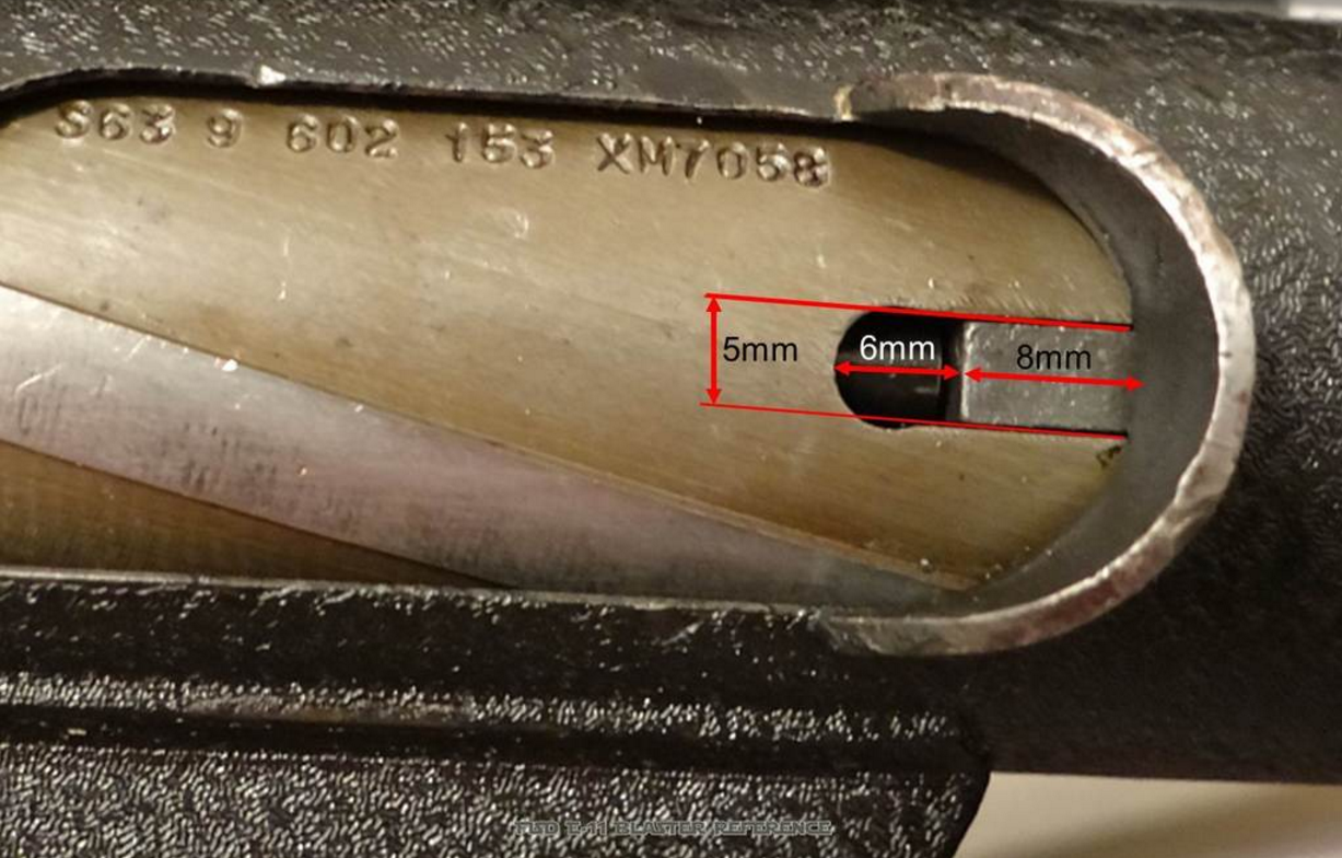
Charging handle:
Gap between handle and slot with bolt closed: 3.5mm
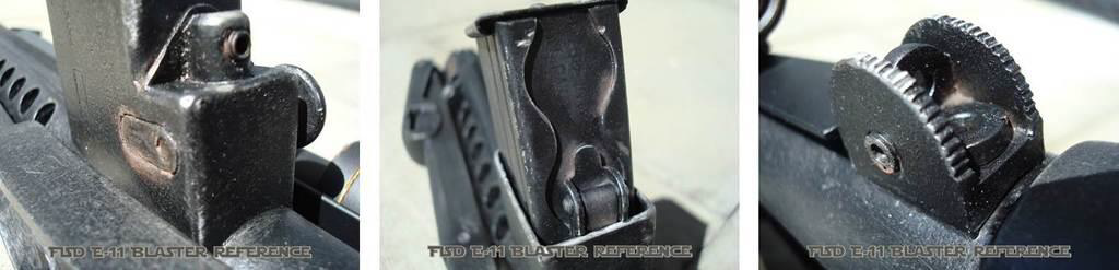
Rear sight:
Fitting a rail - run an 8-32 tap through the 100 meter peephole, then use an 8-32 X 1/4" hex head
Steel receiver tube:
1.5" OD X 1.37" ID X 0.065" Wall
-
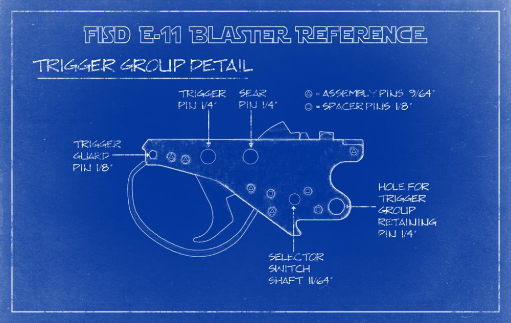
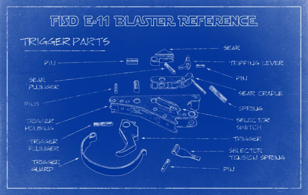
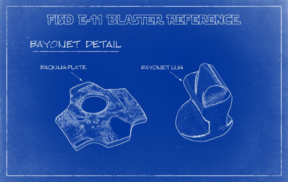
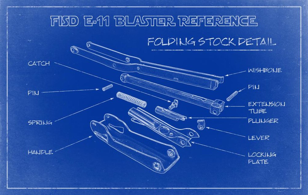
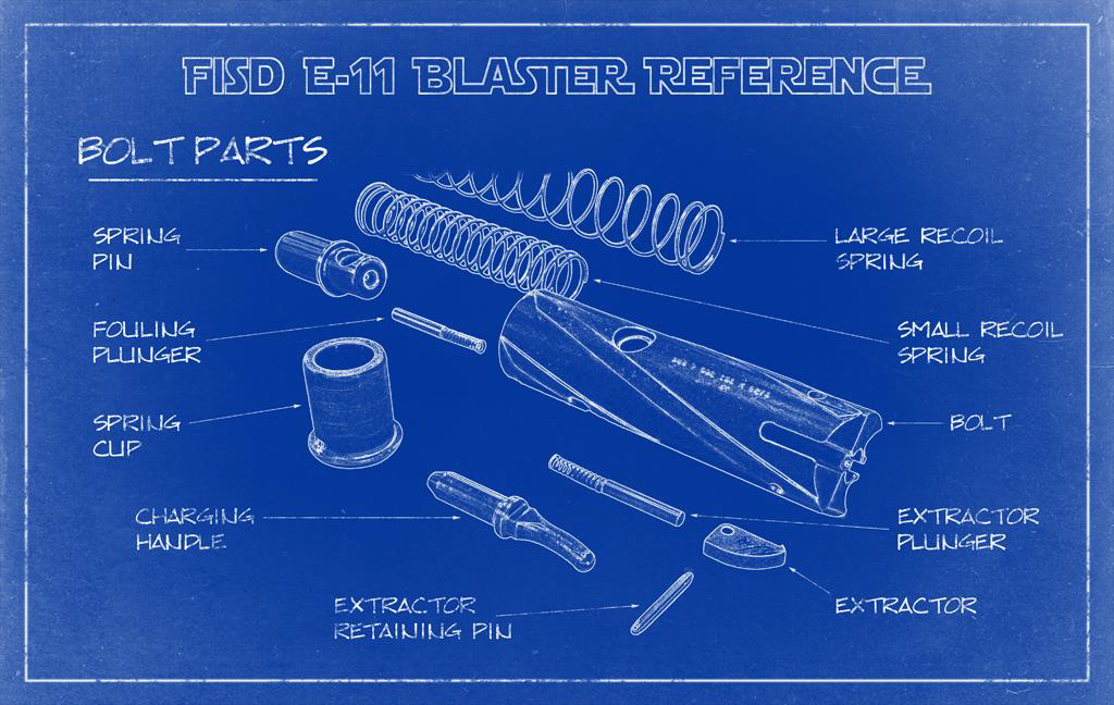
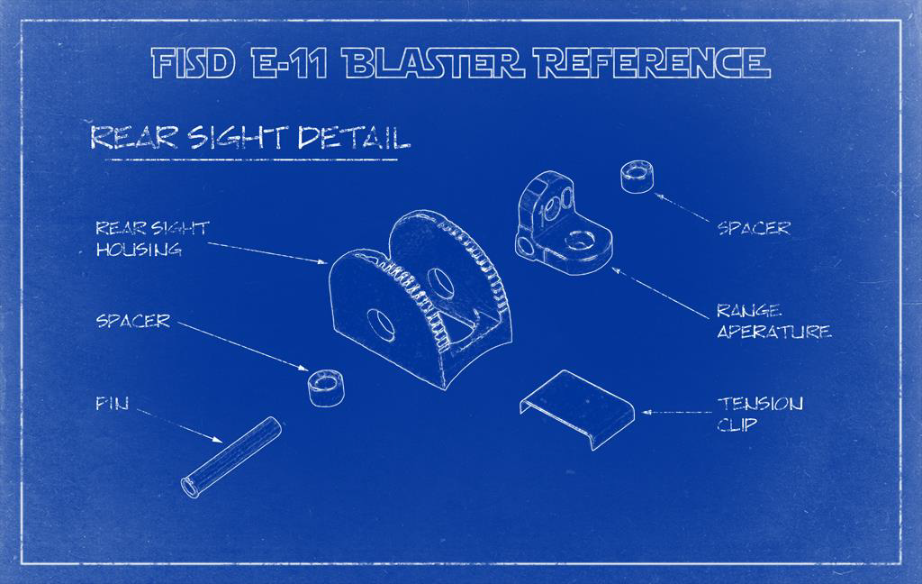
#30 - Blueprints
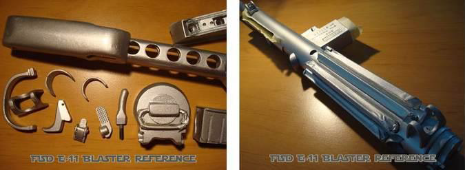
Before starting with the actual blueprints, here is a link to many photos of a precisely cleaned Sterling parts set.


-
2
-
-
#29 - Weathering
Mod A: The dry-brush method is the only way to add weathering, if your kit has simply been spray painted in flat black without any metallic paint layer underneath. It simply means to reduce some metallic looking paint on a brush to a very little rest, so it only leaves some thin paint "scratches" instead of a thick glossy wet surface. This technique adds a lot of realism when carefully used on parts, representing steel or metal. However, do not do this on your T-tracks and grip as those parts are not made from steel. For the scope and Hengstler counter it may only be done with brass color. Be aware the counter bracket was made from brass, but not the counter housing with the window. This was grey plastic. See end of this chapter for weathering on scope and counter.
Mod B: In case you decide to do a paintjob with multiple layers, including the metallic-grey or steel-like color, you can choose from 2 different techniques:1) weathering edges and corners with fine sandpaper will result in having nice metal effects shining through the black color, looking like heavy usage. 2) during the paint process you can alternatively mask off some spots of your metallic looking layer with a masking fluid or candle wax. Leave these masks until the last layer has been applied. After removing, it will look like real paint chips.

Mod C: A combination of all weathering methods (dry brushing, sandpaper and maskings) can help making your build look more realistically.
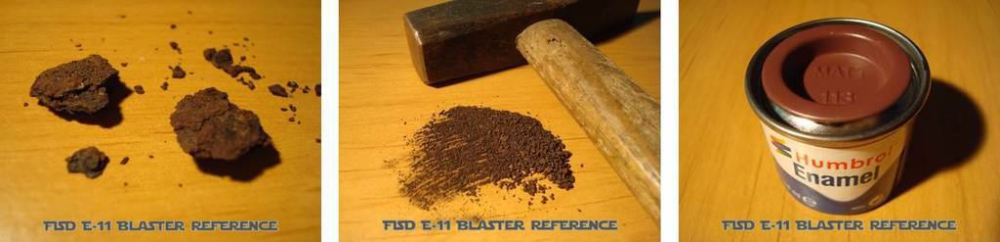
Mod D: Real rust can be milled to fine powder, which can be added in just a few spots where the real Sterlings had rust. Powder can be brushed onto the last paint layer while this is drying, or it can be mixed into rust color paint (like Humbrol 113).

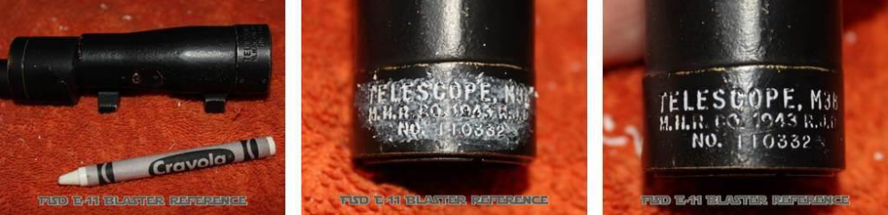
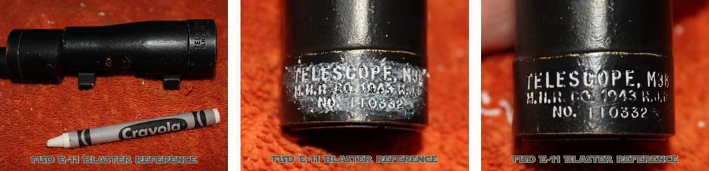
On the scope you can use the dry-brushing method and the sandpaper weathering, while the paintchip method is a bit too much. The other techniques simply look more real on this part. The imprints in your scope can get filled with white crayon. Any excess can be removed with a cloth. If the imprints are filled only partially it helps making the scope look really old and used.
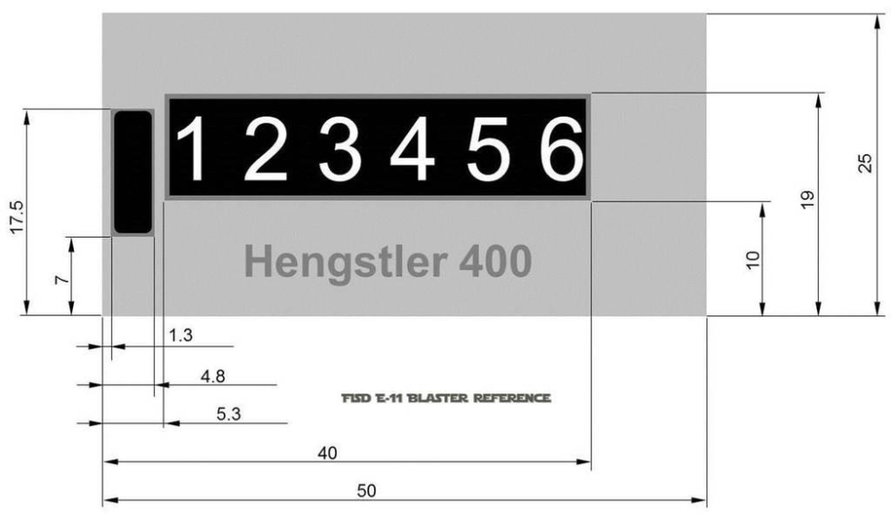
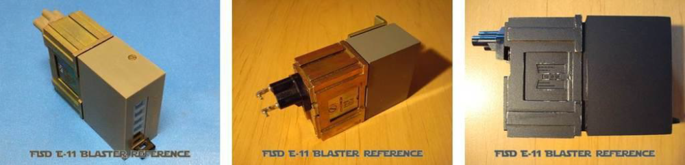
On the counter you can use the dry-brushing method and the sandpaper weathering, while the paintchip method is a bit too much. The other techniques simply look more real on this part. The unpainted counters below show, only the bracket was brass while the cover was grey plastic. Bear this in mind when doing dry-brushing to avoid having brass at the wrong counter half.
No weathering on T-tracks. These should have flat black or semi gloss black with no weathering at all.
Important: Whenever doing weathering (no matter what kind of), ask yourself how the real part would look like after being used for many years. Surfaces will be worn through, paint will come off in stressed areas, there will be paint chips where metal hit metal (like on the bayonet lug or the magazine well), moving parts may leave fine scratches and so on. Also weathering in reality looks sometimes different as on posted pictures, because some cameras have problems catching subtile weathering. You have the parts in hands and you decide about how much weathering you go for. But sometimes less is more and makes the whole thing believable. Try to avoid overdone weathering, even if it is fun doing it. -
#28 - Painting
It is highly recommended to wear some form of respiratory protection when working with spray paint. All surfaces that will later be glued can be covered with masking tape, so you save yourself from laborious paint removing for better adhesion. In case your kit parts got heavily sanded or dusted during the build, it might be an option to wash all parts again like shown in chapter #03. Before adding any paint to a part, make sure these have fully dried and use a primer first. When applying primer and paint, try to keep the layers thin, as several coats of thick paint will reduce the details on the surface. This is especially important for paint jobs with multiple layers and structured paint. Avoid any paint tears on your build - these were only on the TK helmets.
Decide how you want your blaster to look like. Flat black finish with no weathering like seen at the Death Star? Heavily weathered Tunisian Bapty from Tatooine? Crinkle paint as the real Sterlings had? You see, there are various ways to build a screen accurate blaster. The same can be said for the paintjob itself.
Mod A: Simply use flat black spray color on all parts for a factory-new look. Gloss black is not recommended for the gun's main body.
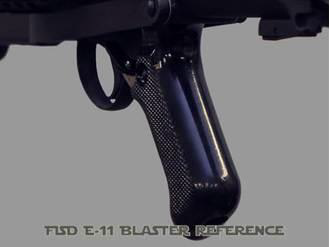
Mod B: The grip from the original Sterlings was some kind of black plastic, which can be recreated with semi gloss or gloss black paint.
Mod C: Parts in the trigger group and the inner bolts were made from metal. Check reference pictures and use some metallic-grey or steel-like colors for these.

Mod D: Using two slightly different kinds of black on separate parts can make your build appear much more realistically. Attention: Separate your build parts in two groups: 1) components representing the Sterling. 2) additions by the prop makers for turning it into an E-11 blaster (scope, scope rail, counter box, power cylinders and T-tracks). Do not use different types of black within the gun's body.
Mod E: In case a dry-brush weathering (see chapter #29) is not sufficient for your build, you can integrate a layer of metallic-grey or steel-like color after priming and before applying the black paint. When later weathering edges and corners with sandpaper, this will result in having nice metal effects shining through the black color, looking like heavy usage. Alternatively you can mask off some places before adding the black paint. Masked spots will later look like paintchips. Attention: This is only to be used for parts of the main gun and the power cylinders - not for other additions like scope, scope rail, counter box and T-tracks. Full resin builders will have to cover the T-tracks with tape, as these are one part with the receiver tube and can not be separated.
Mod F: To recreate the structured surface of some real Sterlings, you can integrate another paint layer - crinkle paint or hammered finish paint. Attention: This is only to be used for parts of the main gun, except the grip, the trigger section and the magazine. Do also not use this for the additions by the prop makers (scope, scope rail, counter box, power cylinders and T-tracks). Order of layers: primer, metallic grey, structured paint, flat black. The metallic grey is not mandatory if you plan to add dry-brush weathering instead of sandpaper weathering. For the crinkle paint, please exactly follow the instructions on the spray can. The hammered finish paint can be paper dabbed with a kitchen roll paper while drying to add more structure to its surface. Depending on how that layer looks, you could possibly skip the last black coating.
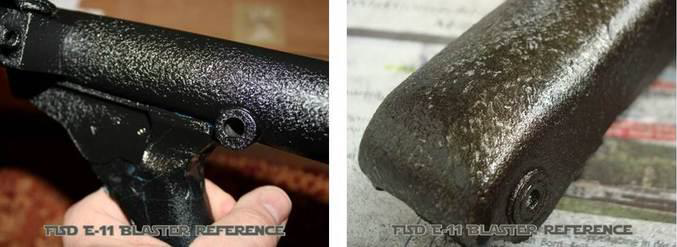
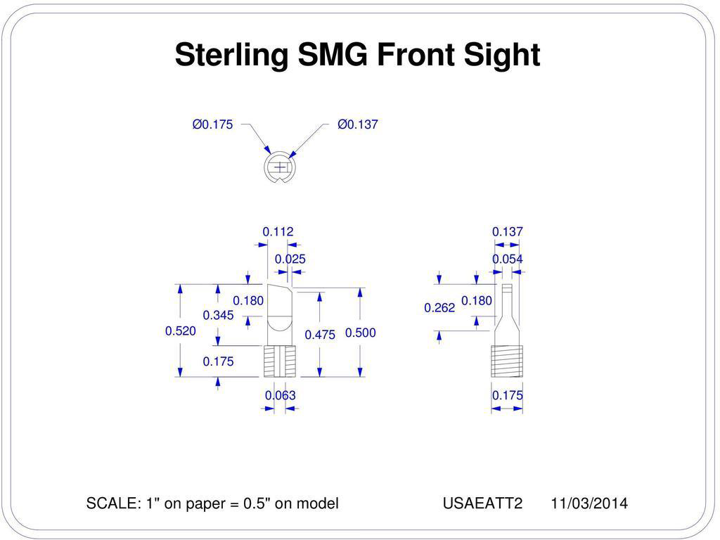
Mod G: The scope should be painted in brass. Before adding the black layer, mask the feets (both feet on bottom and rear foot on the sides too) and run a thin wire through that gap at the front. When the black paint fully dried, you can unmask everything and weather the scope with fine sandpaper. Alternatively you can skip the brass coat, add the black paint and some brass colored dry-brushing.
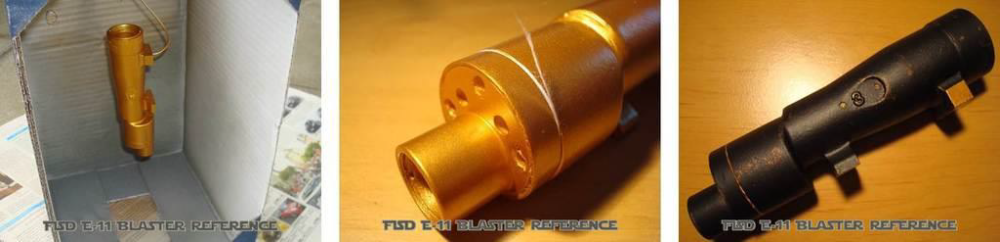
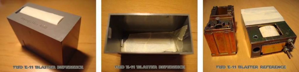
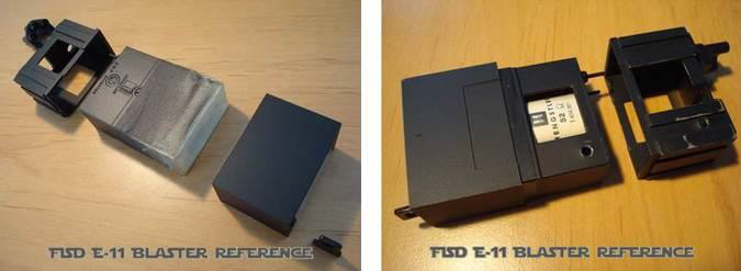
Mod H: The counter should be painted in flat black. Make sure to cover the counter window from the outside and the inside. Do the same for the number rolls, as you don't want any paint fog on these. When using a real counter, cover the coil if you later still want to have that label visible.
-
#27 - Assembling
As there are various resin kits available, each of them unique in their own way, there is no chance to create a universal step-by-step guide. However, you should begin with selecting your favourite modifications, depending on your kit, skill level and personal preferences. To avoid any conflicts within selected mods, re-check if some of these might affect others. Start doing the individual mods for each part and try not to glue anything at this early stage. Think of accessibility to each part (also the small ones) for painting. Glue only when you can be absolutely sure, you will not have to disassemble that specific section later. Surfaces to glue should be roughly sanded before applying the glue. For resin to resin connections CA glue works best, while resin to aluminium requires universal liquid glue. Whatever you choose, make sure it is instructed for use with the materials in your build.
-
1
-


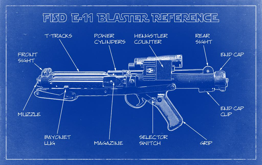


FISD E-11 BLASTER REFERENCE
in ANH BlasTech E11
Posted
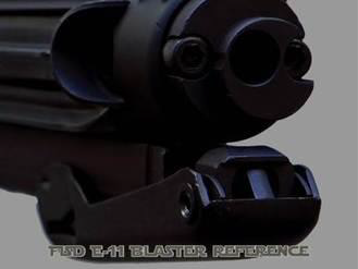
#34 - Greeblies
Some (not all) E-11 blasters in Episode IV (ANH) had a few greeblies but up to now it was not possible to determine exactly what these were. Below is a reference photo. The first two greeblies are placed on the left side of the folding stock (close to the bayonet lug and above the trigger), while the last one sits on top of the scope.
Photos of fan-made reproduction pieces for better resolution:
The first two greeblies are hard to identify, the last one seems to be a 14 prong IC socket.
The greeblies are not recommended for Basic Approval, as most GMLs are (currently) not aware of their existence.