


kev011
-
Posts
51 -
Joined
-
Last visited
-
Days Won
2
Content Type
Profiles
Forums
Gallery
Articles
Media Demo
Posts posted by kev011
-
-
That is the classic TK. We are discussing the TFA TK. Refer to this thread for what you seek: http://www.whitearmor.net/forum/topic/30831-anovos-tk-armor-preorder/page-1
Thank you! I'd typed avonos in the search engine and this was the only thread that popped up, thanks for the specific direction
-
I just heard about the "classic" kit price today online with the $350 price tag. I thought I'd check in here to see if anyone else was talking about this?!
-------------
Will this pass the strict 501st guidelines from your guys point of view? I hadn't thought about entering into a TK suit until I saw this price tag. Knowing there is still going to be all the work of assembly and such, if this would pass for 501st events in the end without severe mods, I could be in!
Let me know what you all think. I sure could use a nearly complete suit of white armor to go along with my E-11
Cheers, Keven
-
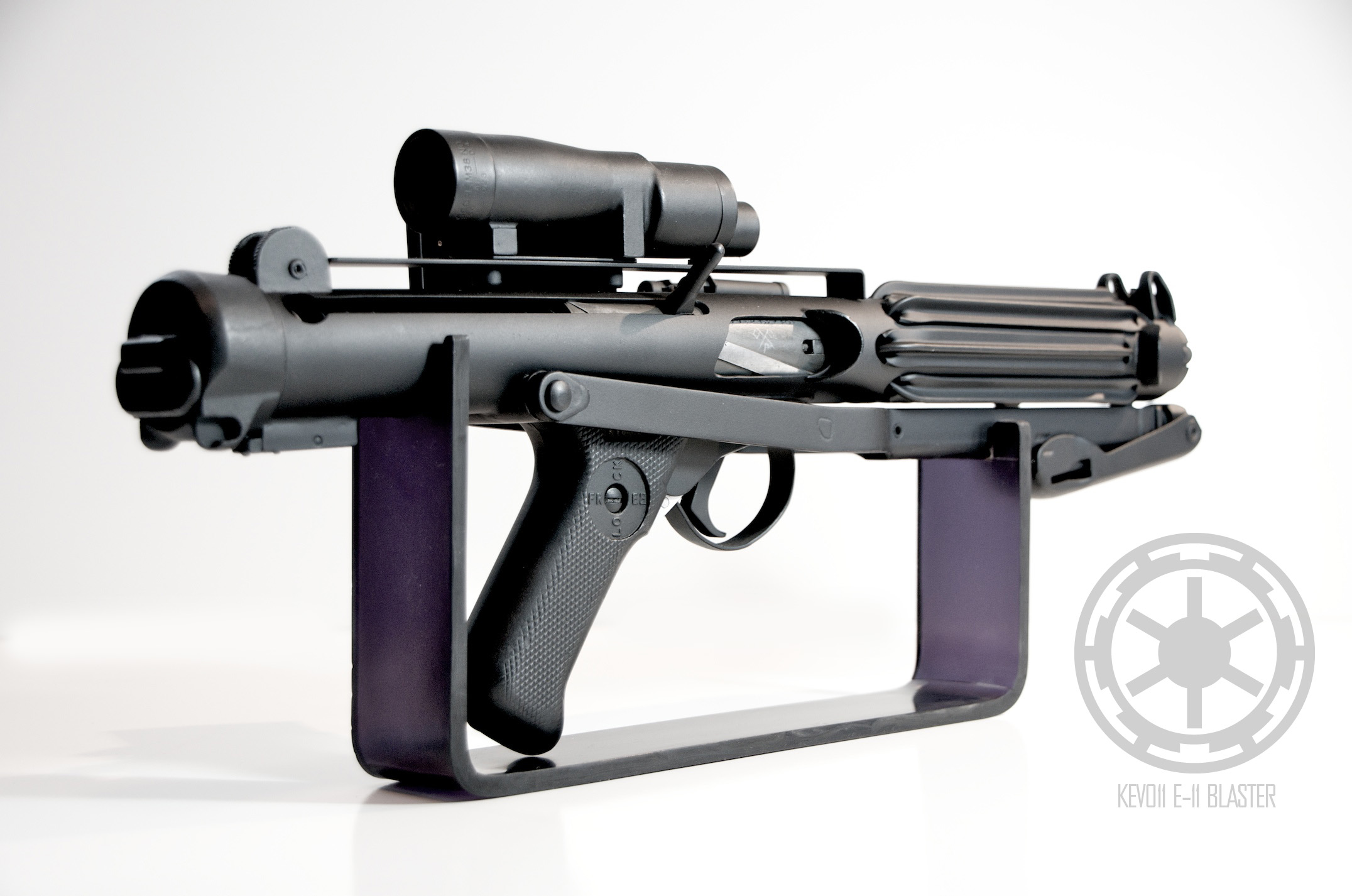
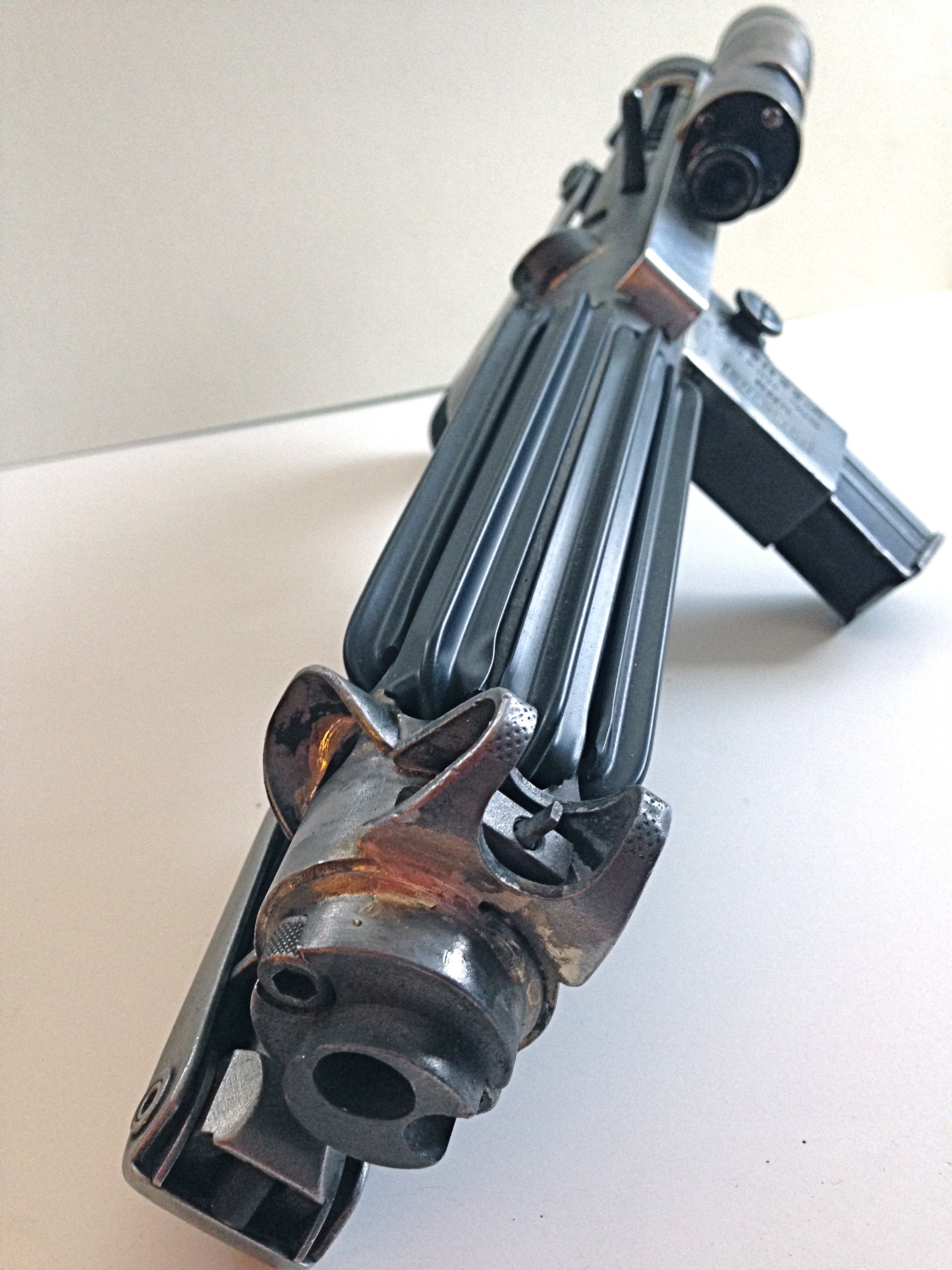
Since I'd finished my E-11 Blaster build, I had some left over pieces parts that I've been thinking about how to utilize. I had two scopes that I made into one.
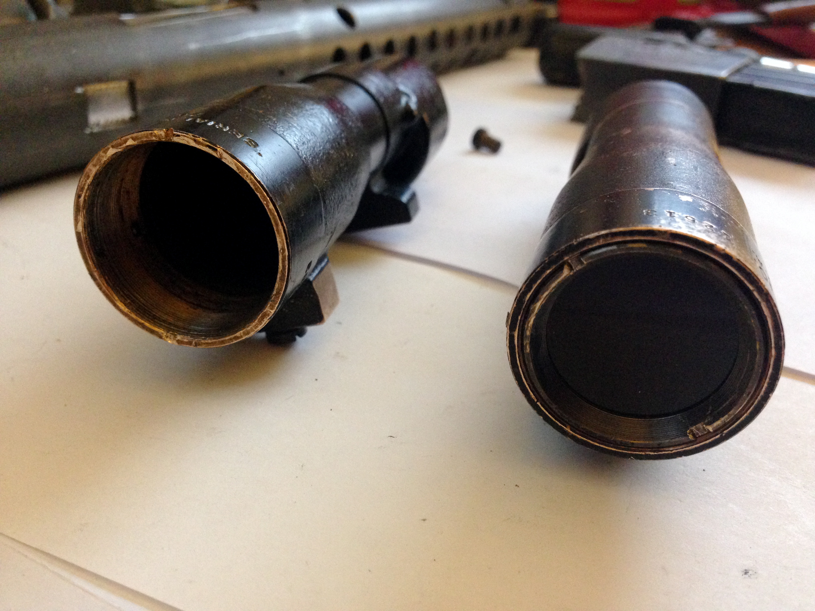
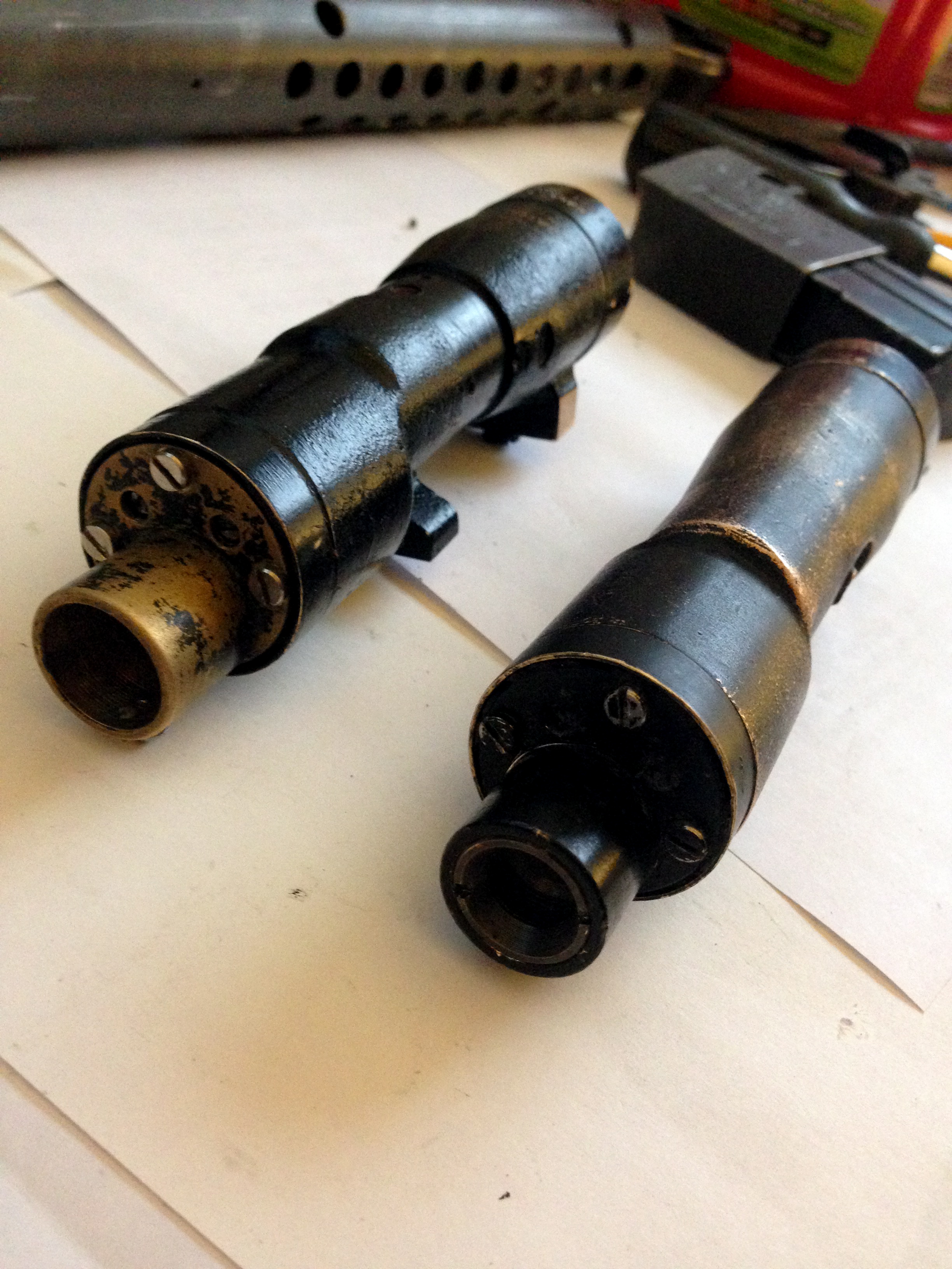
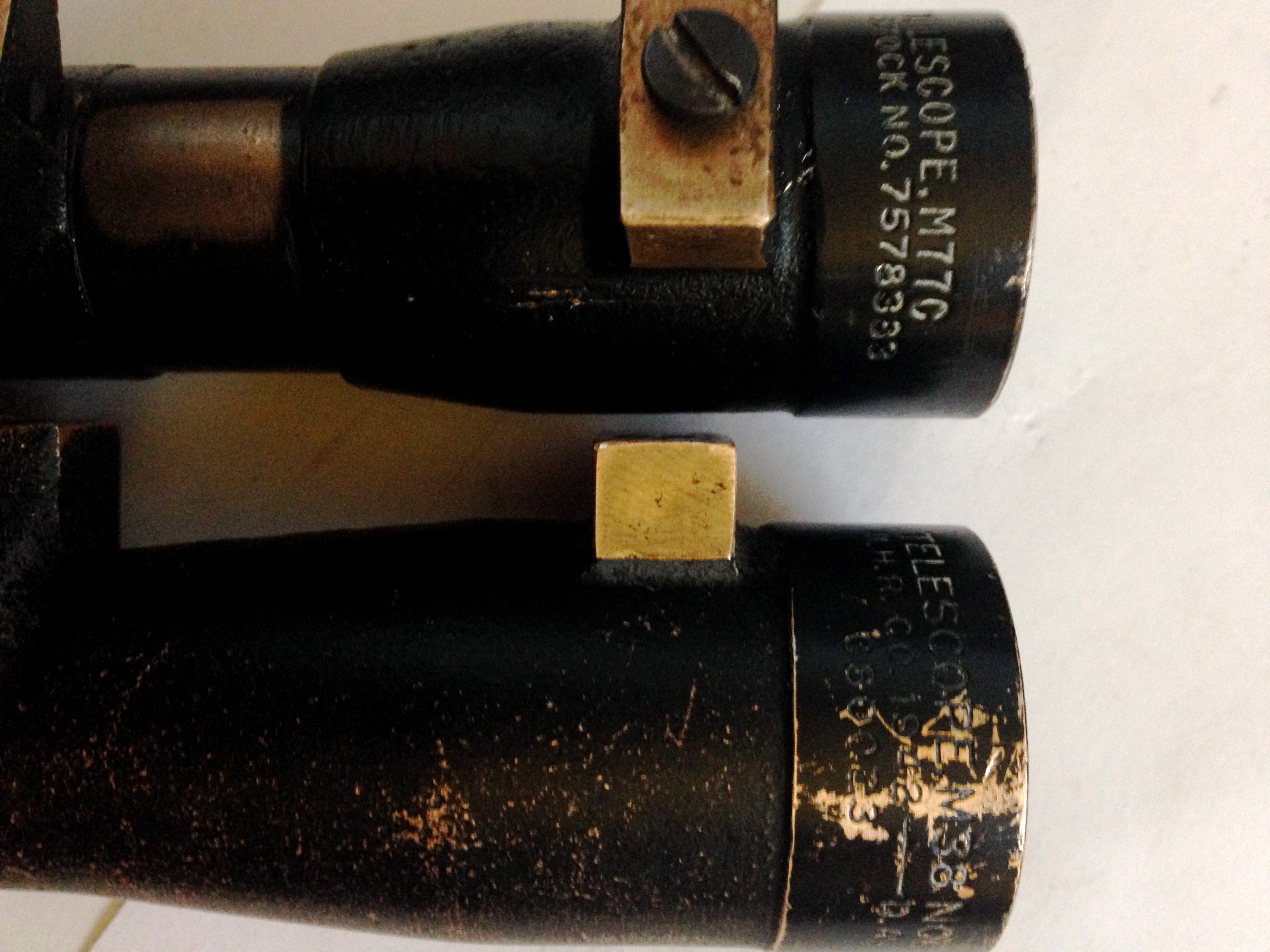
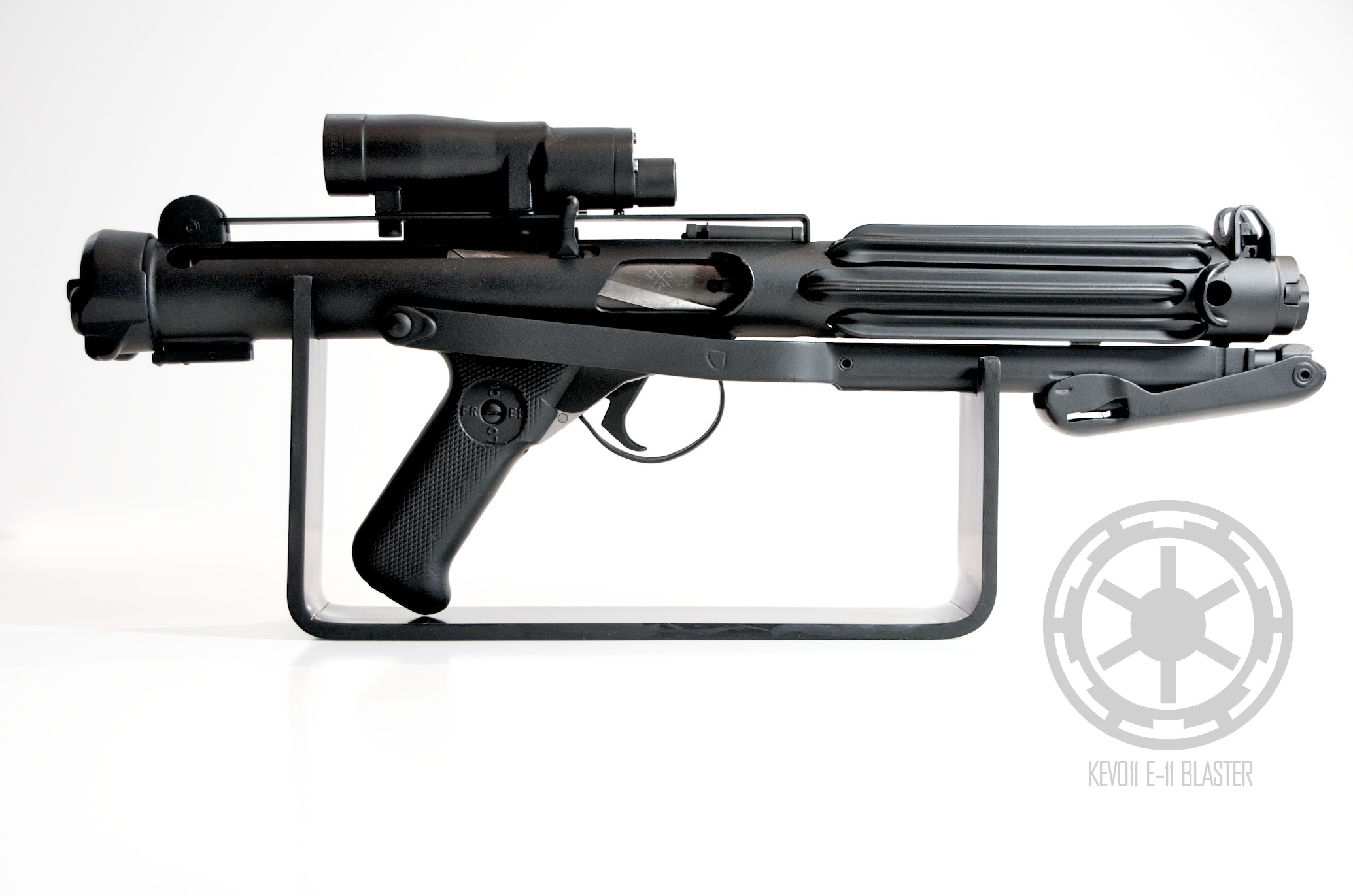
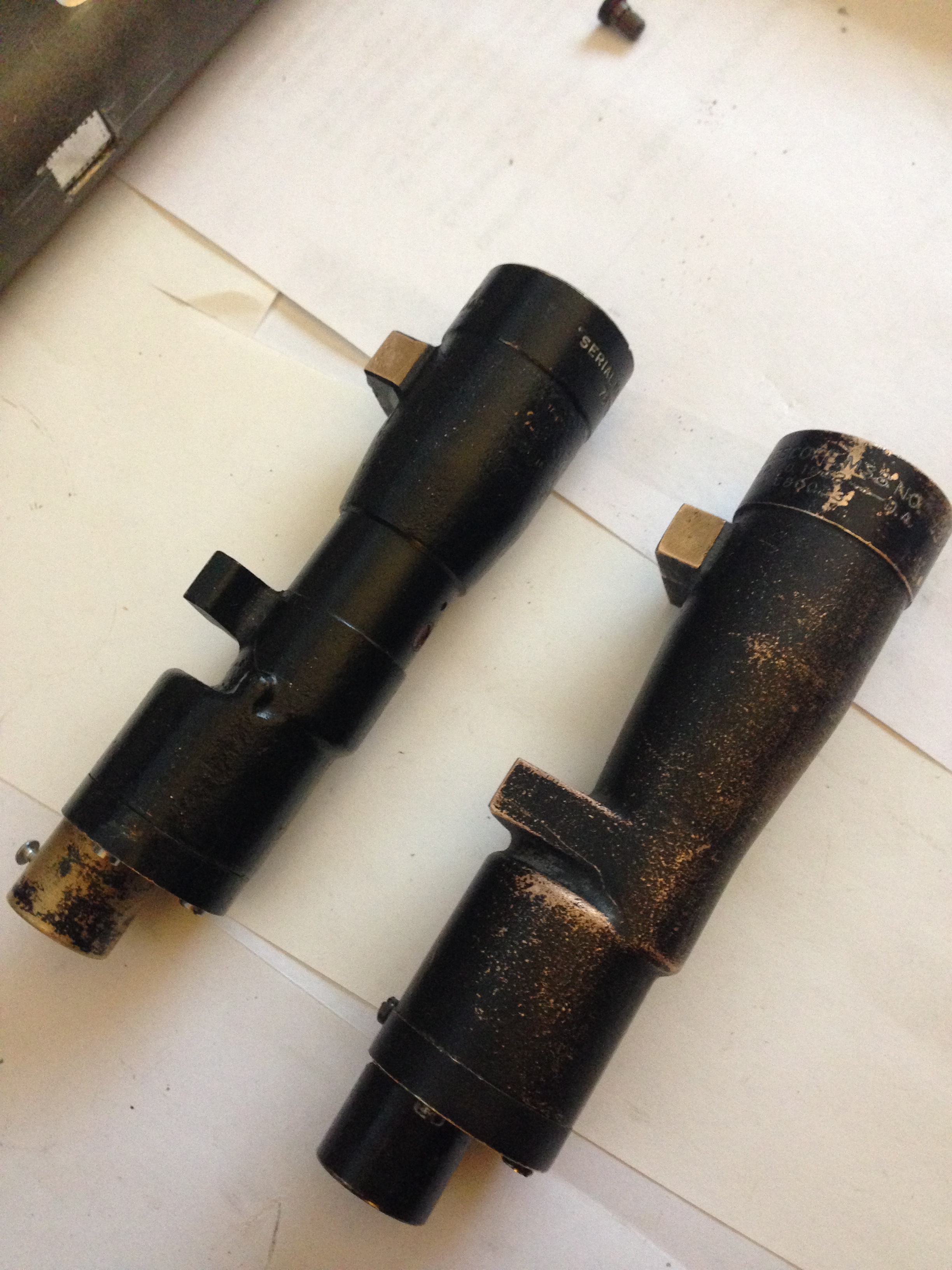 I took all the guts and glass parts from an M77C and put it into my M38 to have a scope that would appear as an authentic E-11 Blaster from A New Hope.
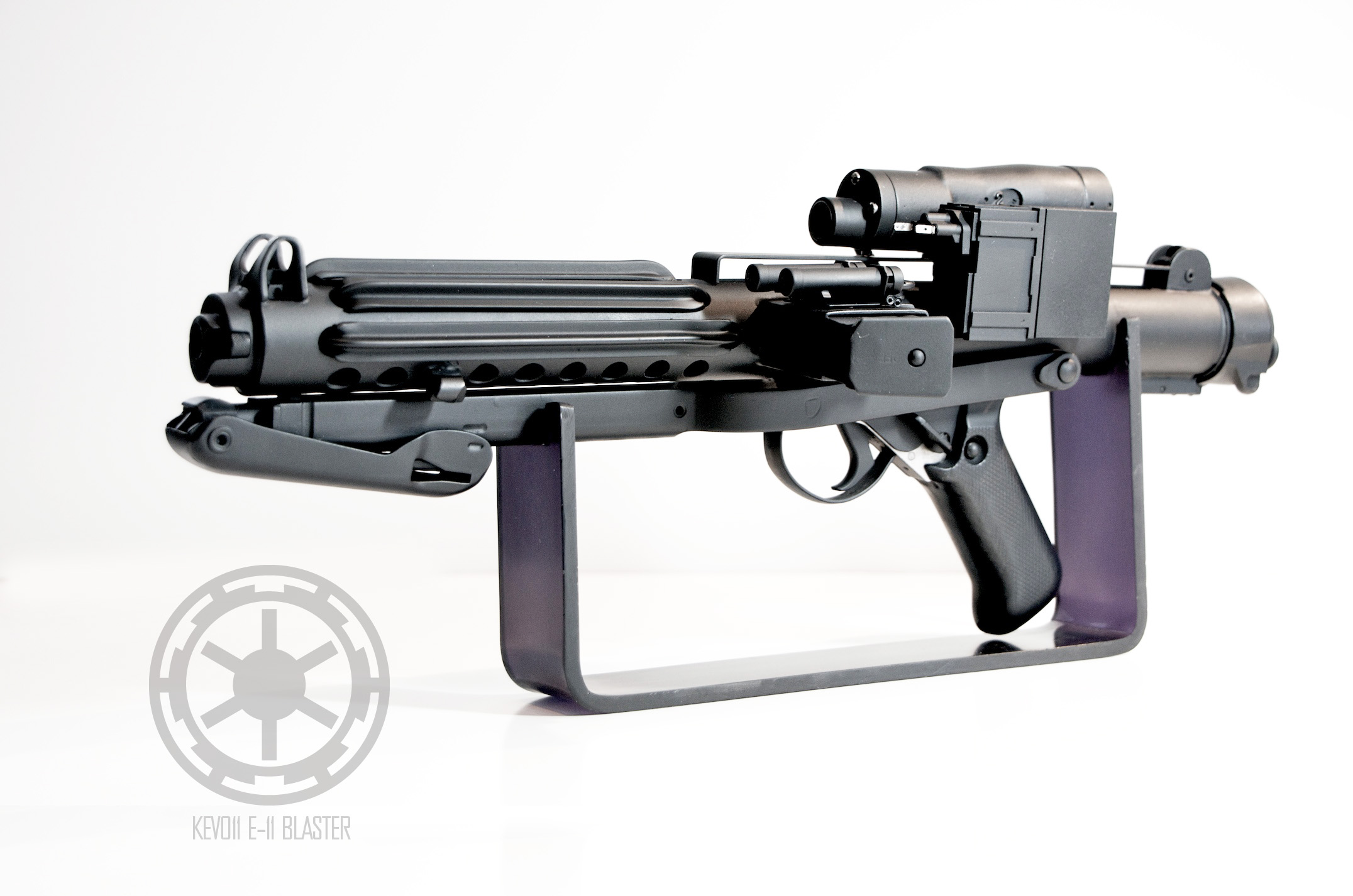 I saw some threads on what scopes were used vs not used and recall seeing a graphic that mentioned taking out the center section of those unused scopes and thought about how to perhaps make a decent attempt at creating an M19 from one of those scopes. I came up with this:
 I realize that this would be some work to get it there and that you could probably take this several steps further to create a very accurate representation (and possibly functional) M19 look-a-like.The question is, has anyone attempted this yet? I'm curious how close of an end result this idea could yield.
 -
Excellent job on the blaster
Thank you, Jkno!
Did I see somewhere you did a MerrSonn Power5 Blaster? I've been debating on either doing one of those or perhaps a esb Han Solo DL-44 next. I'd prefer to stick to bad guys and I'm currently on the hunt for pieces parts for a Mauser build up
-
I just can't stop looking at it! Just incredible!
Thanks so much, gazmosis! Much appreciated.
-
Thanks Art! You're very lucky to have a complete Sterling, your build should be a snap!
-
Aaron really nailed it. Pretty much the same process I used doing the carb dip and airplane stripper but I did use a wire wheel on my angle grinder on some parts of it to help things along. I also recommend putting down card board boxes below you chemical dipped parts and this will soak up the black gunk and the chemicals of the airplane stripper as well and can go to the trash when done. Chemical dip will evaporate quickly if you leave it uncapped, one thing you could do is get some old socks and soak them in the chem dip, then put them on either end of the gun so they are sitting on the metal, then place the soaked socks on the gun in a heavy plastic bag (or double bag it) and leave over night. You may need to repeat this process over a few days but it will soften that coating up and make your chem dip go further.
Just finished up mine if anything can help you out here:
http://www.whitearmor.net/forum/index.php?/topic/29486-Chopped-up-Sterling-project-%3D-E-11-Blaster
-
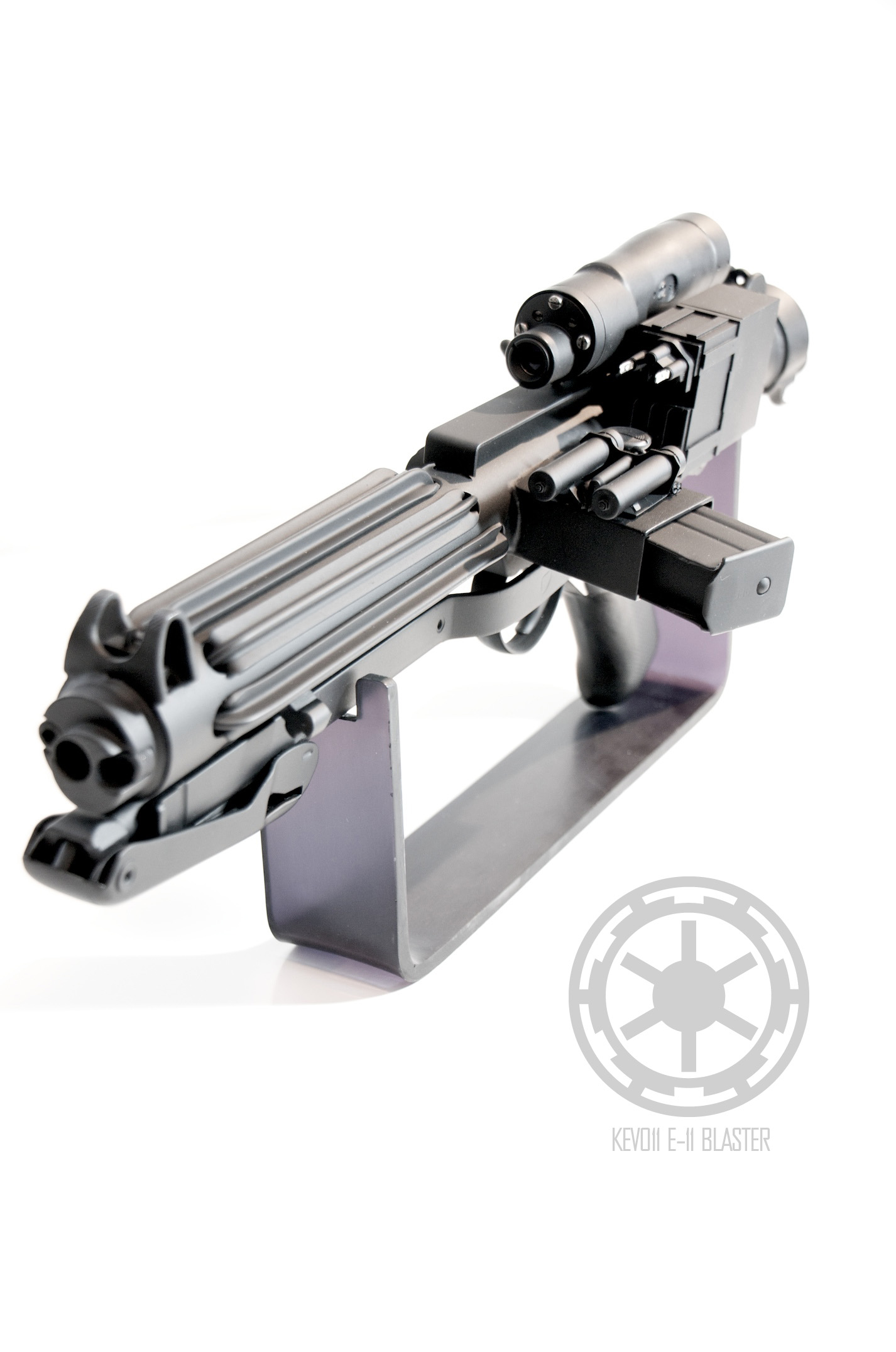
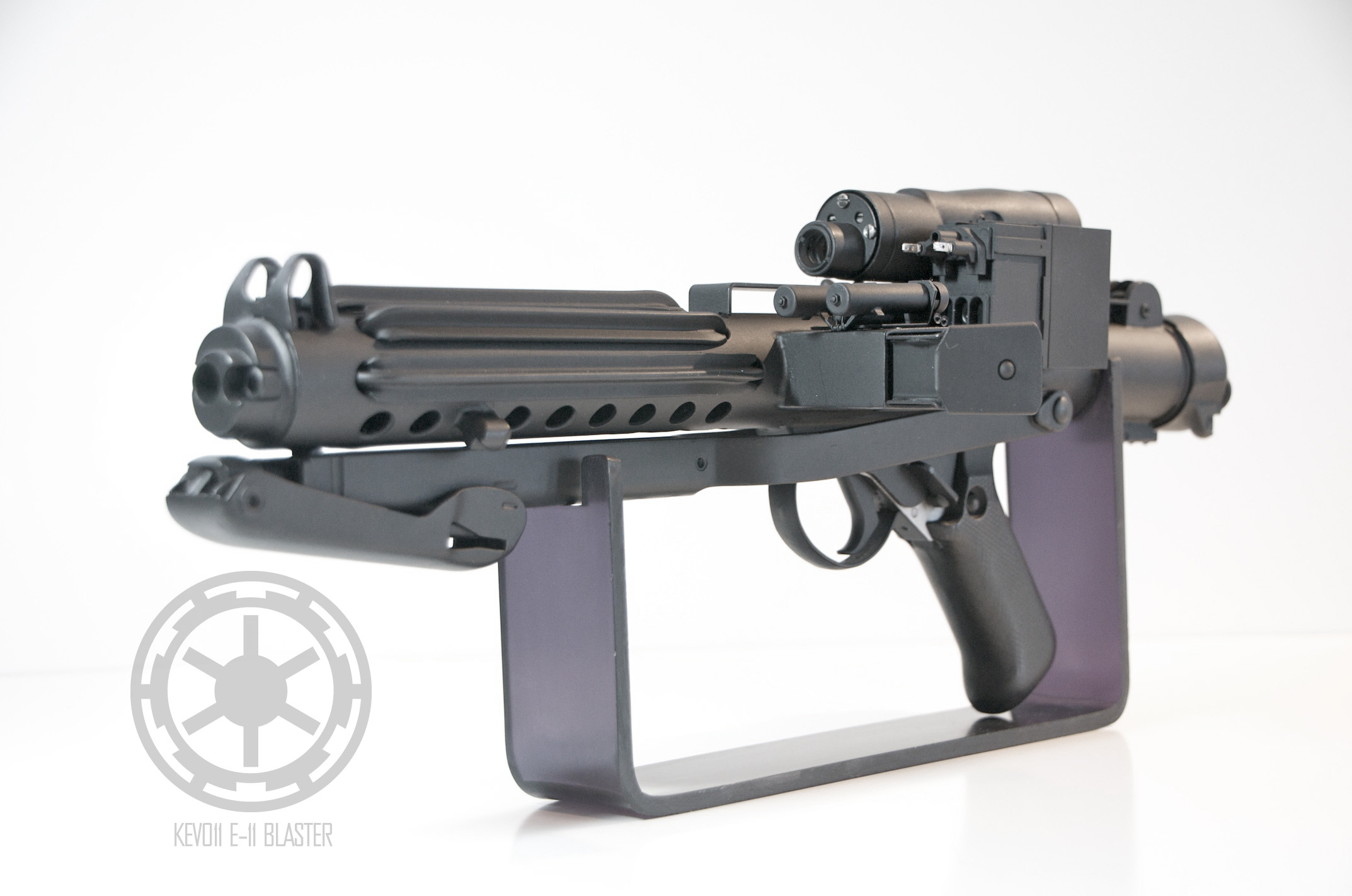
Looks great Kev! Love the blaster stand. So simply but stylish. Does it get much wobble having a relatively thin base?
Thanks for the compliments!
The stand is completely temporary. I made it specifically so I could take some photos today. It's pretty stabile for what it is. The footprint is 2" wide by 10" long. The biggest issue is some of the weight of the counter and the magazine offsets the balance. If I didn't rush it I could have cut the square mount pretty close to the folding stock so it wouldn't turn at all.
I have plans for building a nice base for this but came up with this quickie solution for today.
-
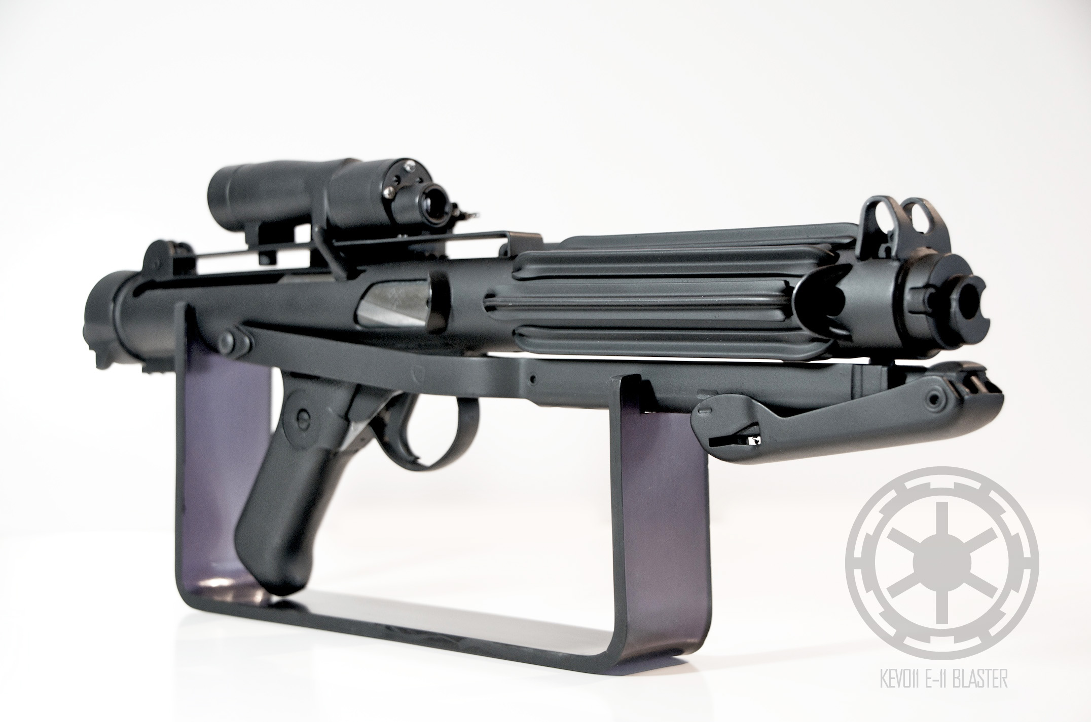
About two months later, mission accomplished
My thread about it here: http://www.whitearmor.net/forum/index.php?/topic/29486-Chopped-up-Sterling-project-%3D-E-11-Blaster
-
Thank you, Sandtrooper!What a fantastic E-11!
-
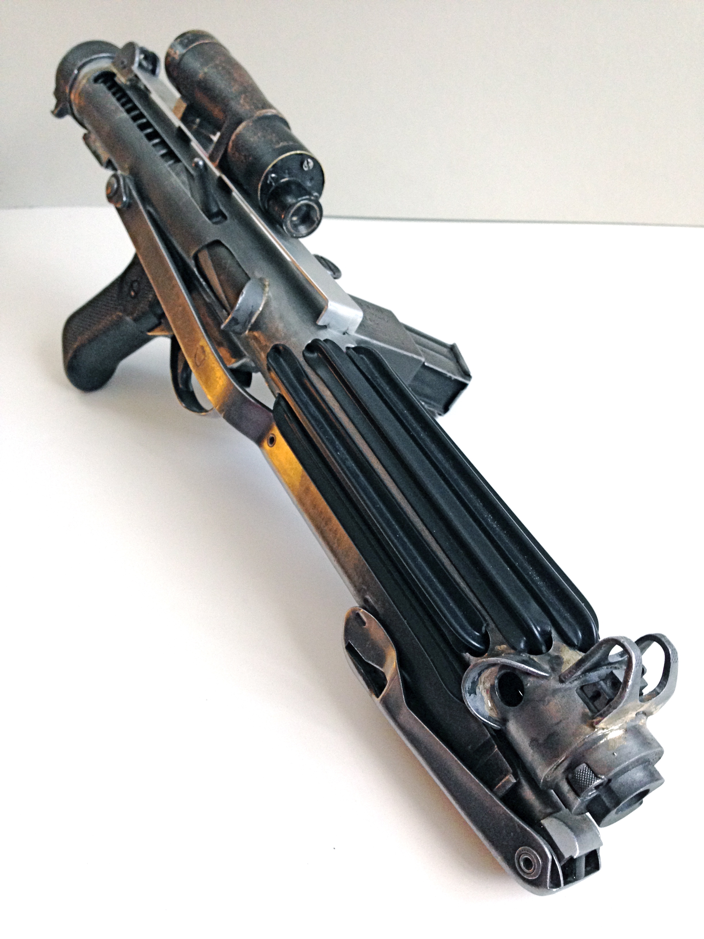
If anyone is still following along, here's the update:
And… DONE!
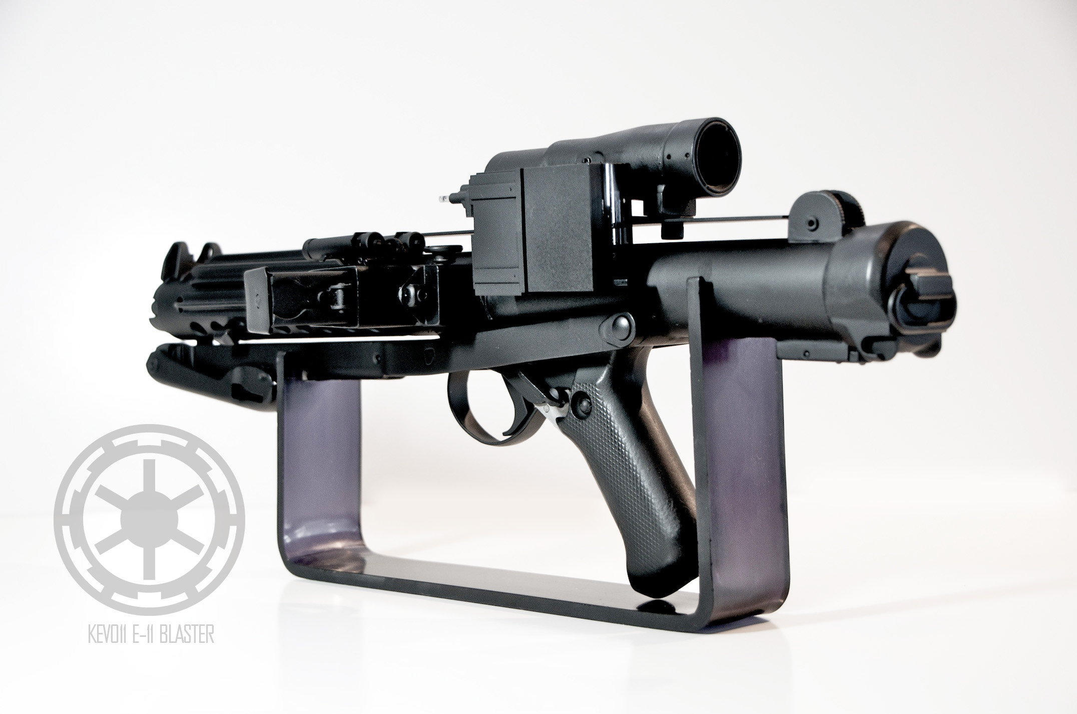
 I finished a few days ago (thursday) on the painting and assembly on Saturday. The massive snow storm that hit kept me from posting as I was digging my family out to civilization and also had to stay home with my son due to school closings. But, it's complete.I'd mentioned that I was using DuraCoat (which I don't recommend) I thought it was magic in a can but I don't have positive things to say about the experience, so I'll just keep it at that. If you'd like more details about it or if you are considering it, please feel free to PM here and I'll give you some details.Today I bent up a quick piece of plexiglass that I had scraps of to make a quickie stand to shoot this E-11. I've very pleased with how it came out. The only thing remaining is to build a proper stand which I have already in the works (at least in my head).Hope you enjoyed and I've helped out someone out there as much as many of you have helped me in this build. Troopers helping Troopers, right?
-
 1
1
-
-
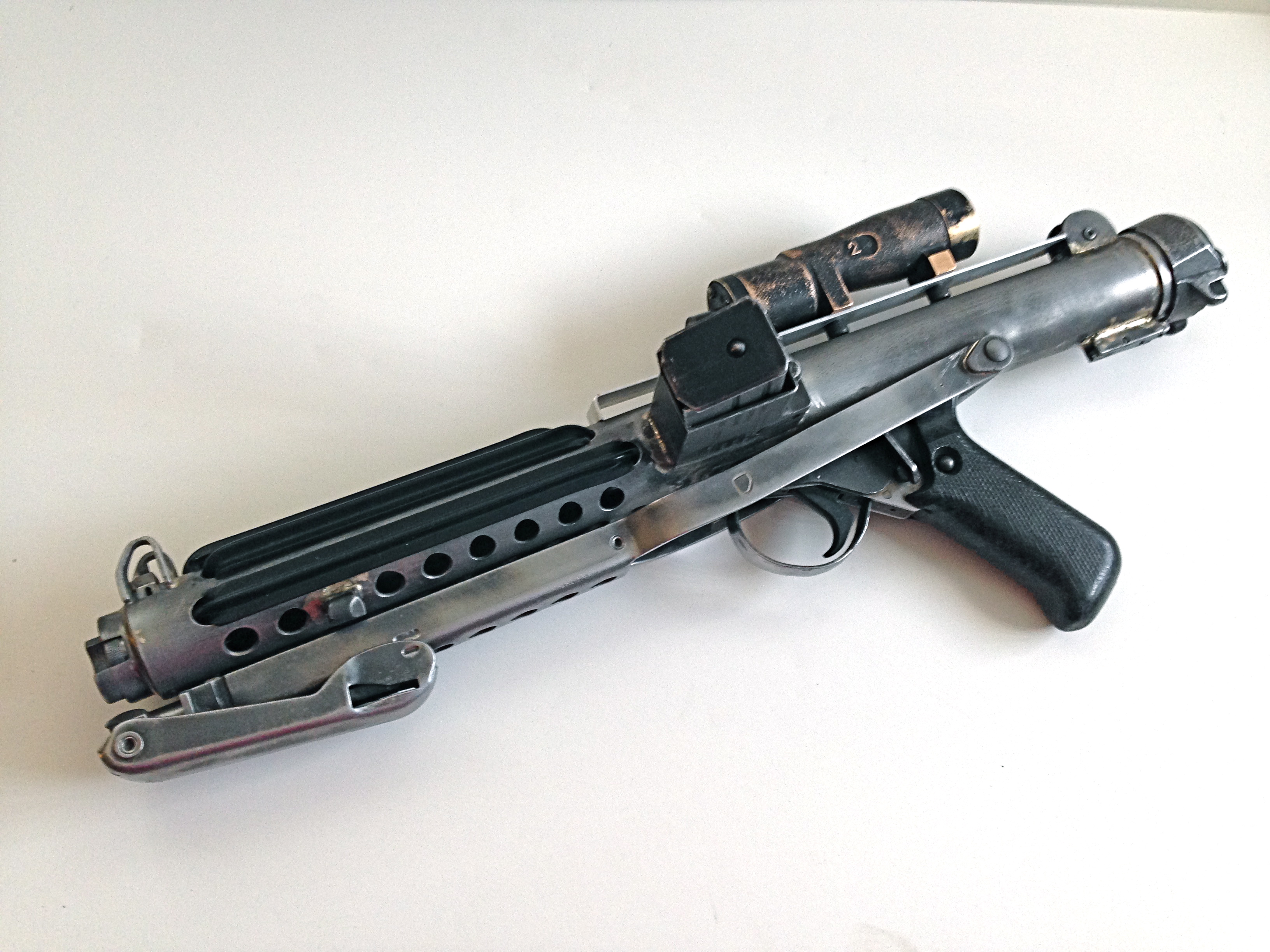
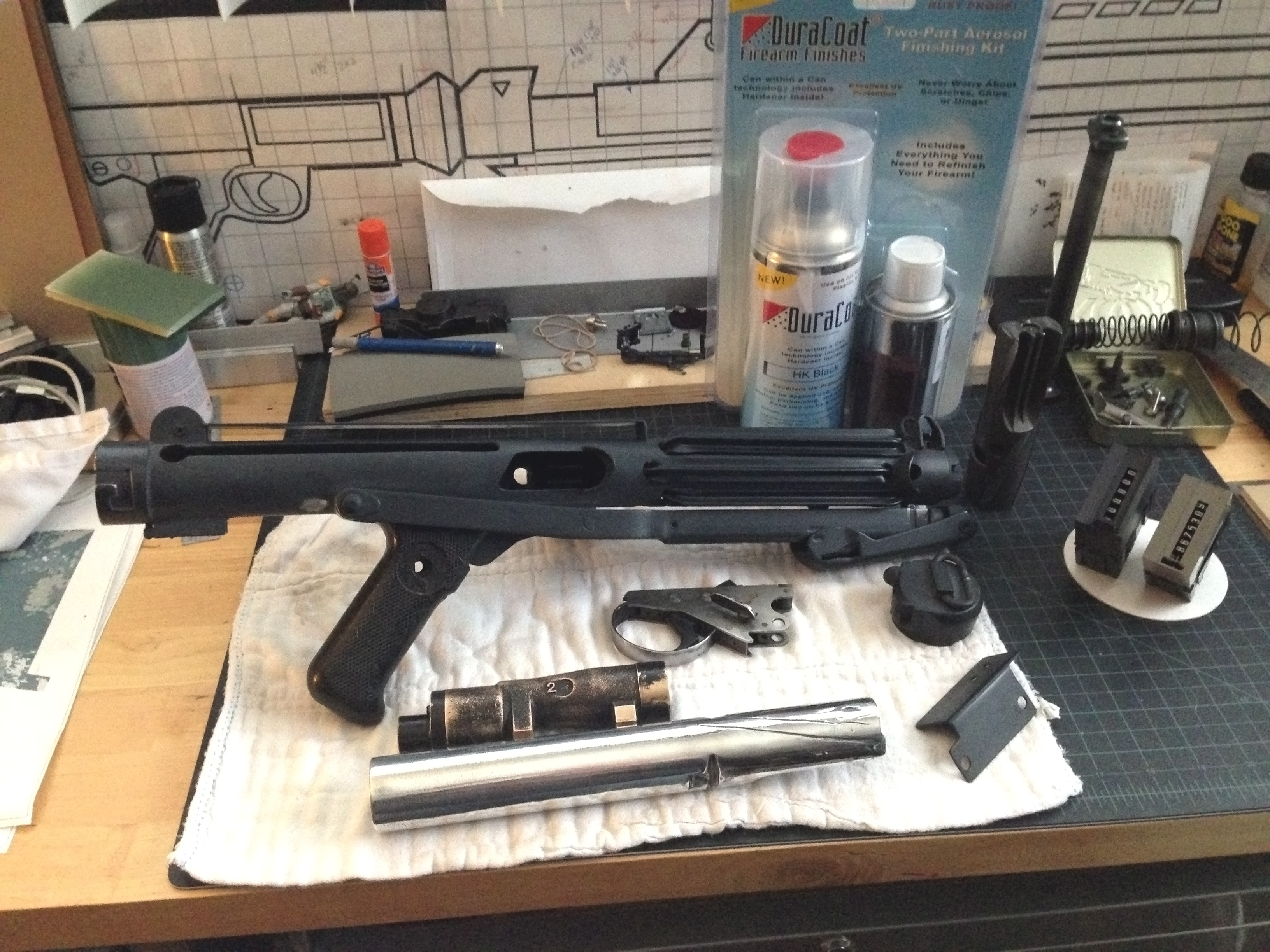 Sorry for the lack of posting on this. Sometimes life gets in the way of fun. I wanted to do a quick update to the thread so it's not completely dead, although it's not seeming to be very popular in the known universe of white armor.I've spent some time sanding all the parts pretty smooth and shot a quick coat of black SEM primer over all the parts to be painted to check my sanding skills. I'm glad I did the practice run of the primer as it let me know I missed a few spots in the folding stock. That area will require some thinking on how to shoot all the areas and not have any bare metal spots. I'm pretty pleased to see things look good! I ordered a Duracoat spraybomb kit with the can in a can tech of hardener plus pigment.I'm currently waiting on Mr Post Man to deliver one of these beauties to me!
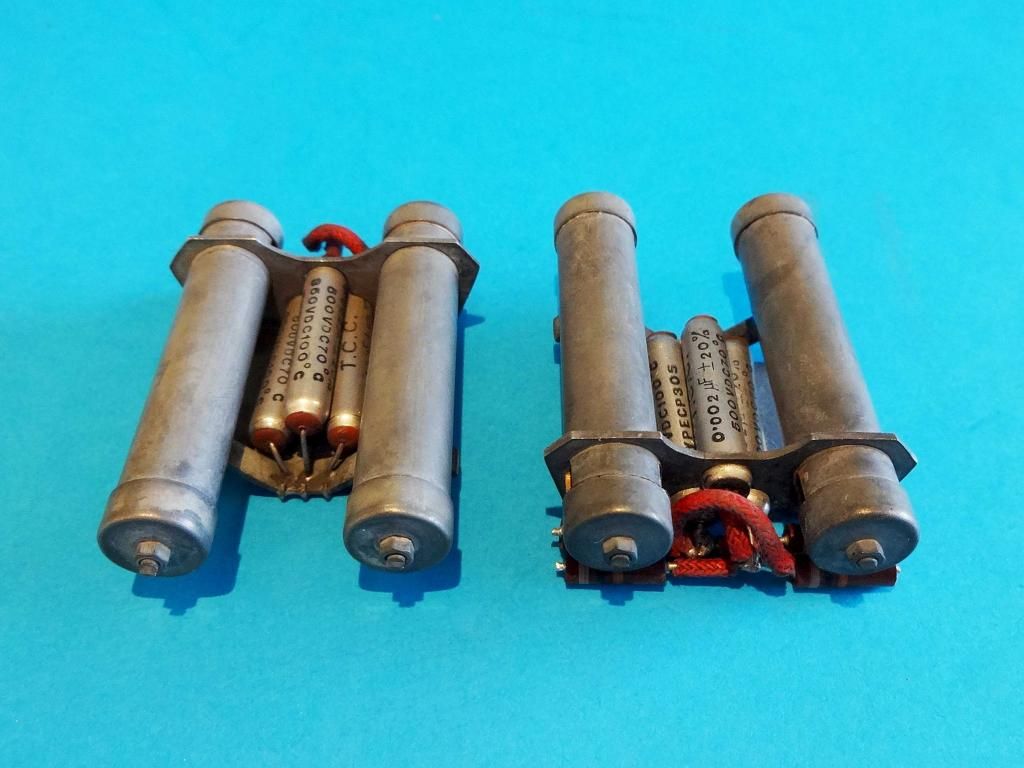 I decided to go with the best and Andy really pulled through on the power cylinders! I had them come naked so I could have a consistent color over the whole blaster. So as soon as they clear customs in Chicago and arrive here, I'll be building a paint jig coming up to harness all my parts, screws and nuts and widgets to easily be able to be painted.Getting close now! I also have some ideas of a blaster stand I may start on soon to really give this build a classy look.Until next time.
 -
I've just had a look at all my tracks as they're sitting on the blaster - some have quite a defined raise at the bend, some almost nothing. I'll definitely fix them up a bit with a combination of more trimming and/or heating.
Thanks all.
Having done this just recently, I feel like the trimming may be a better option. I worked with Roy's T-Track which heated up so fast. I reheated a few areas and it's easy to deform them too easily out of the total shape. If you reheat, take your time and watch your pressure!
-
Looks like you forgot to add in the reset button after reassembling the counter. Either that or you left it out so it wouldn't change your number. Maybe cut it off inside or glue it down so there isn't a blank hole, and it won't reset your number.
I think the counter is a little bit too forward, but it's probably not.
I will generally assemble the front of the counter equal to the first of the 2 holes/screws in the scope. So I would move it back about 1cm.... BUT that is me and was from one screen used blaster photo. I can 100% guarantee they are not all in the same place and your placement is height aligned which is the most important.
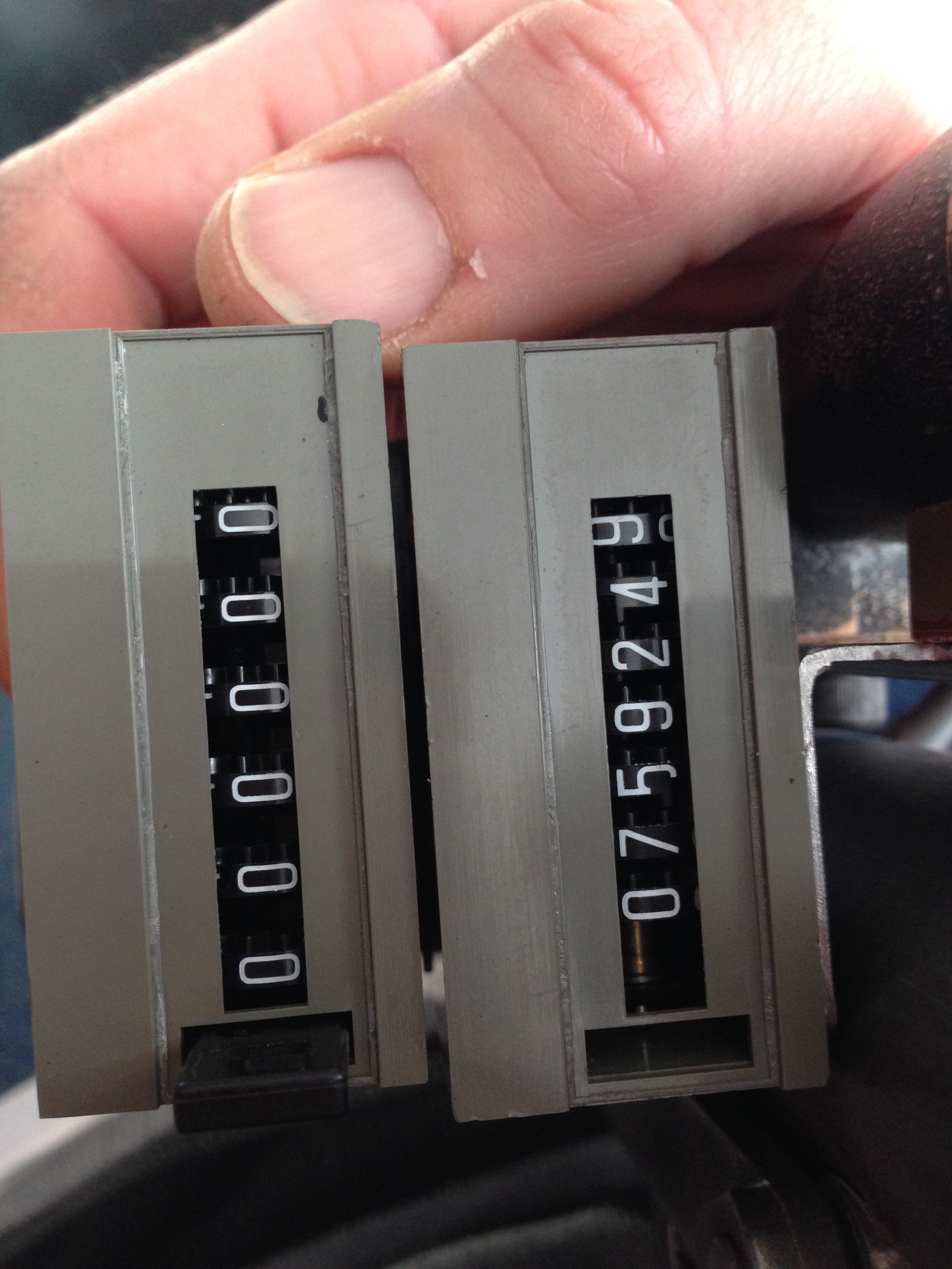
I have two counters. One has a reset and the other is more of a lifetime counter with no reset. These were attached to each other. On whatever machine these were on together I think that one allowed for a daily,weekly, monthly total and the other was purely a lifetime. I wanted to experiment with the no reset button version so I didn't mess up.
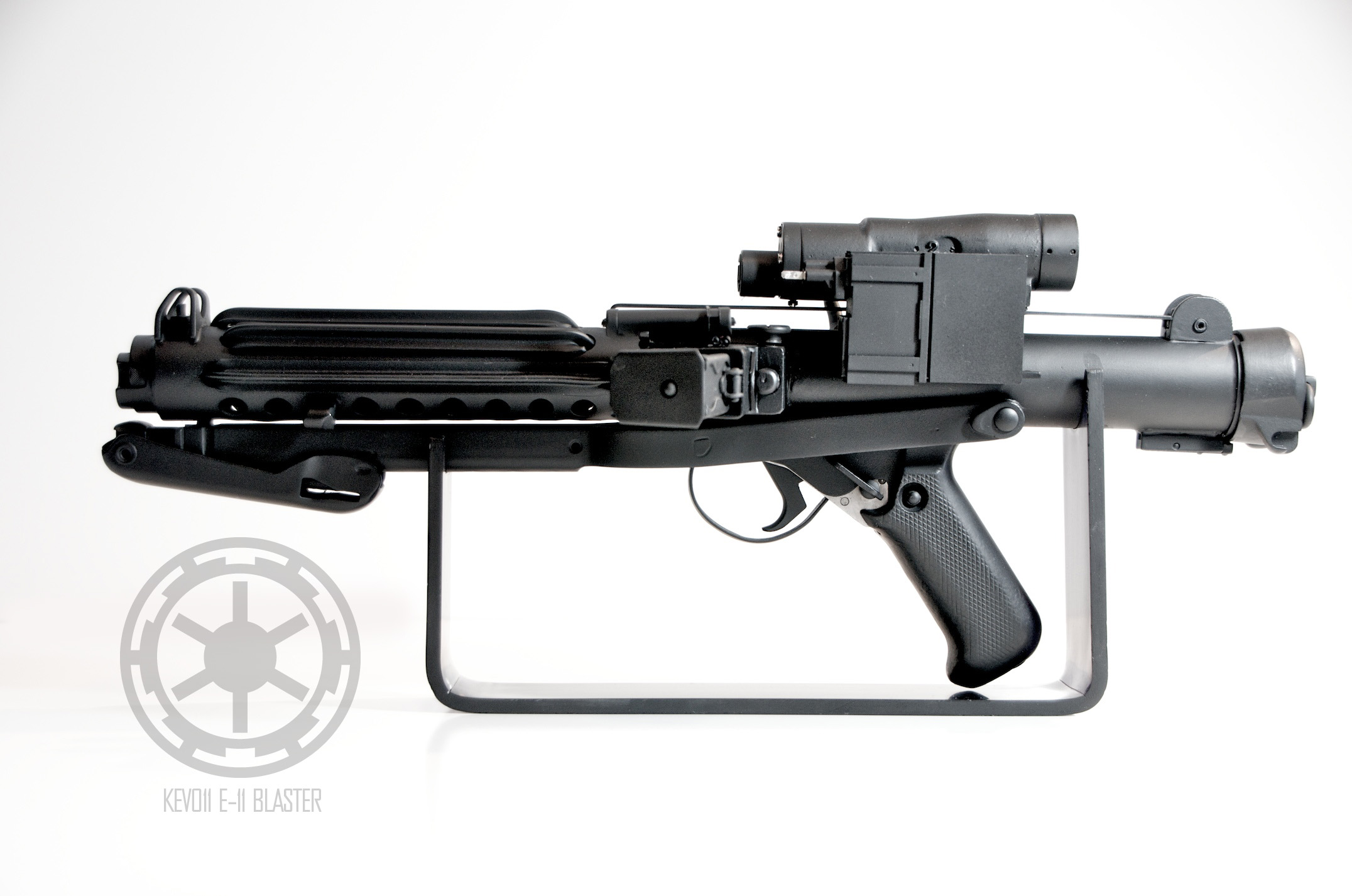
 I suppose the whole scope could be mounted too far forward. I was attempting to align based first on the where the mag receiver was and then to the scope. I tried to align the face of the scope to the edge of the mag receiver and then the plastic tip (not the metal leads) to the edge of the outer ring of that scope. I've seen a few examples of the end of the counter hanging well over the mag release button, but that just makes it a pain in the butt to use.
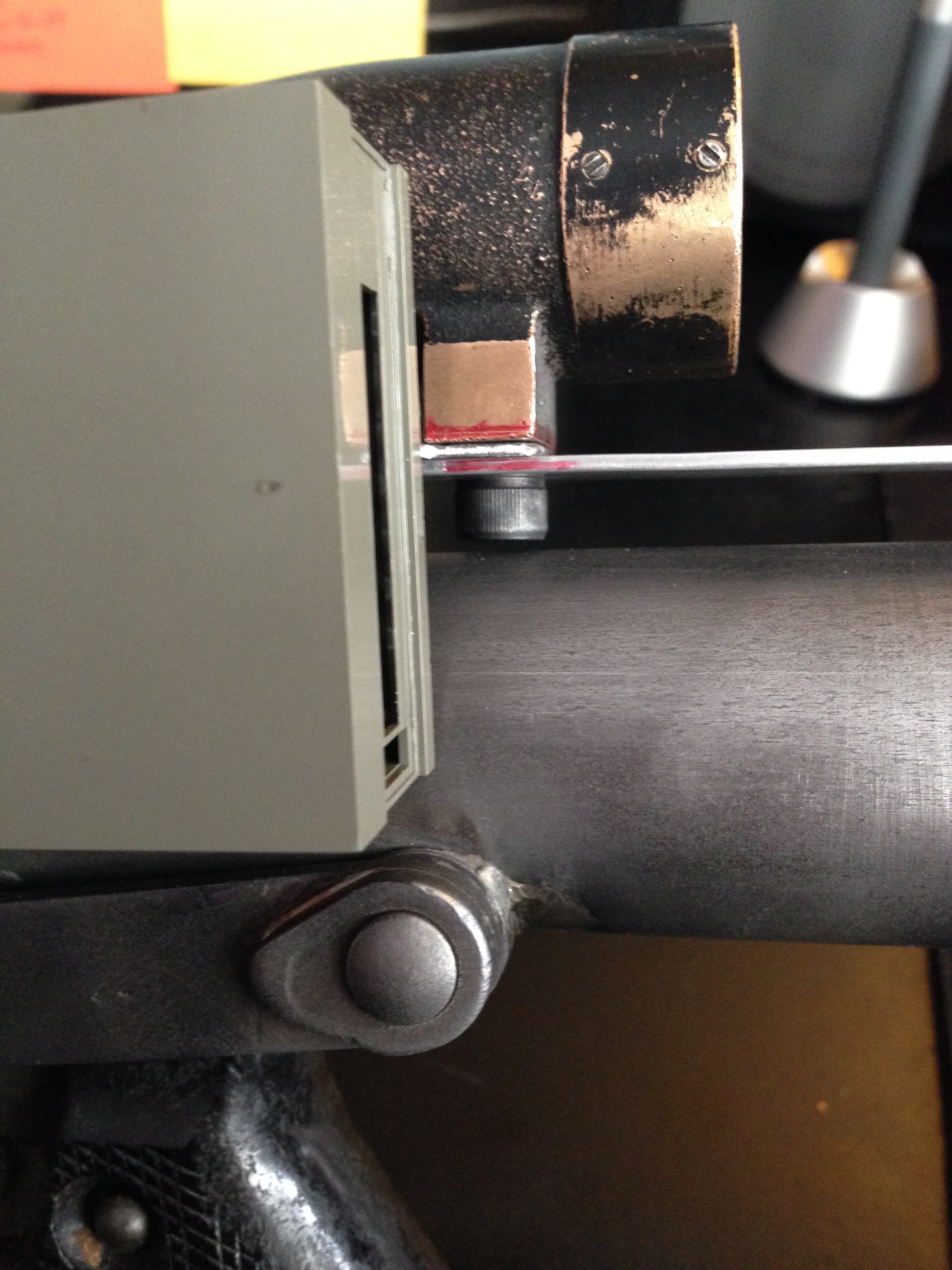 For the rear of the counter, I wanted to align the edge with the rear scope mounting point. This also makes it sit pretty nicely front-to-back with the scope. Maybe I'm way off, but I *feels* right to me.
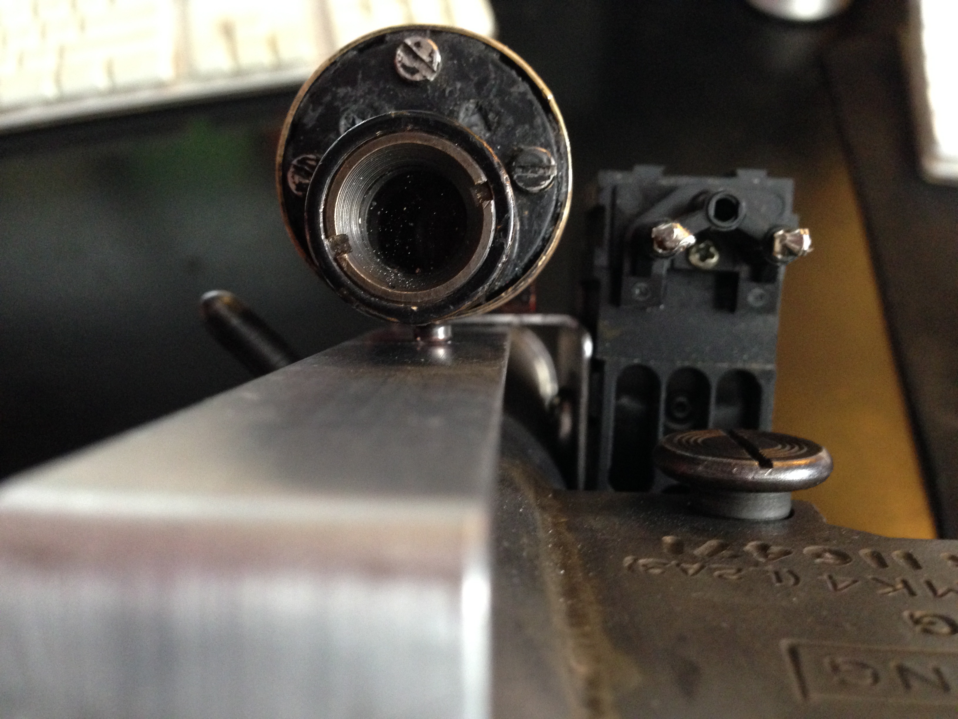 For top to bottom, I tried to match the height to the apex of the front of the scope to the apex of the receiver tube.
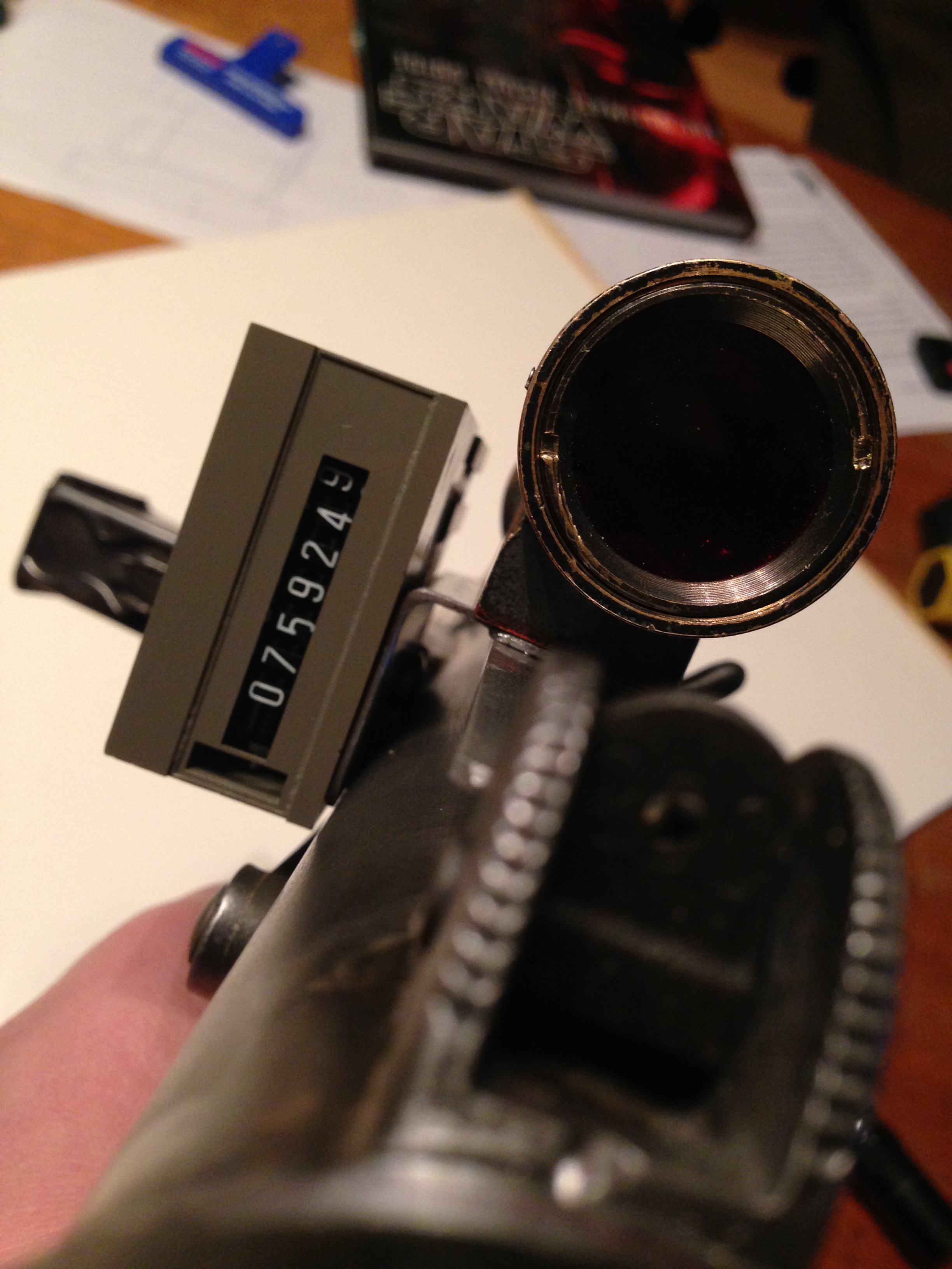 Like I said, I feel like it's pretty balanced, but that's me.
 -
Thanks guys! Okay, now that I had the plan, I just needed to make it happen.
 I bought myself a new tool set to do knurled threaded inserts after discovering them recently. Such a cool item to be able to rivet and have a threaded hole ready to go, all in one!Though these really didn't need to be added to the square tube, I was a little antsy to try it out so this was a perfect opportunity
 The tool allows you to mash/mushroom down, like a rivet and what you are left with is a pre tapped hole ready to go. This did give me a little more bite than what I would have had if I just tapped the 16 gauge tubing.
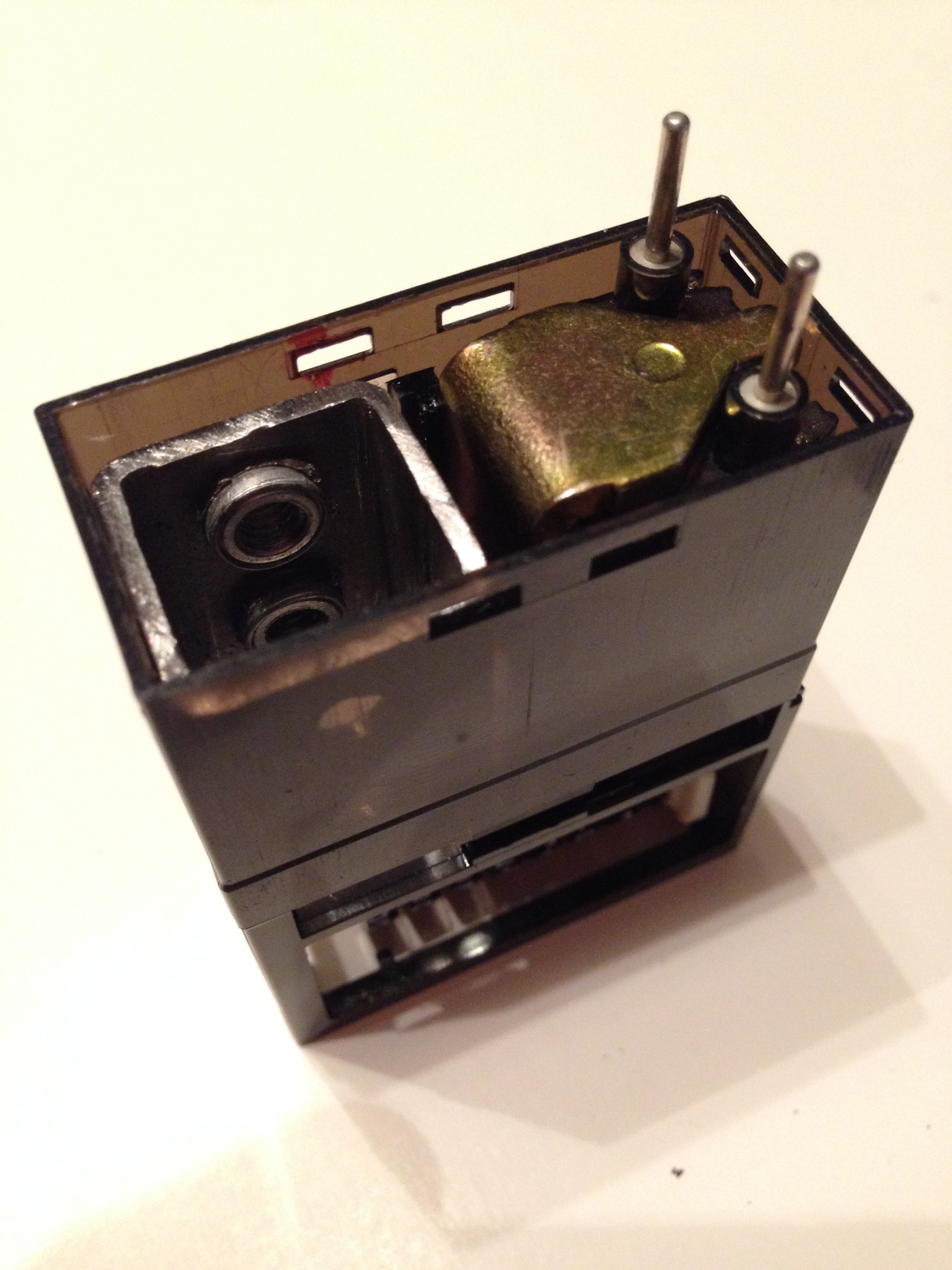 Because there is nothing in that lower area, this just worked out great. If I decide I still wanted everything to work, it still could and nothing is interfered with as far as the mechanics of the counter.
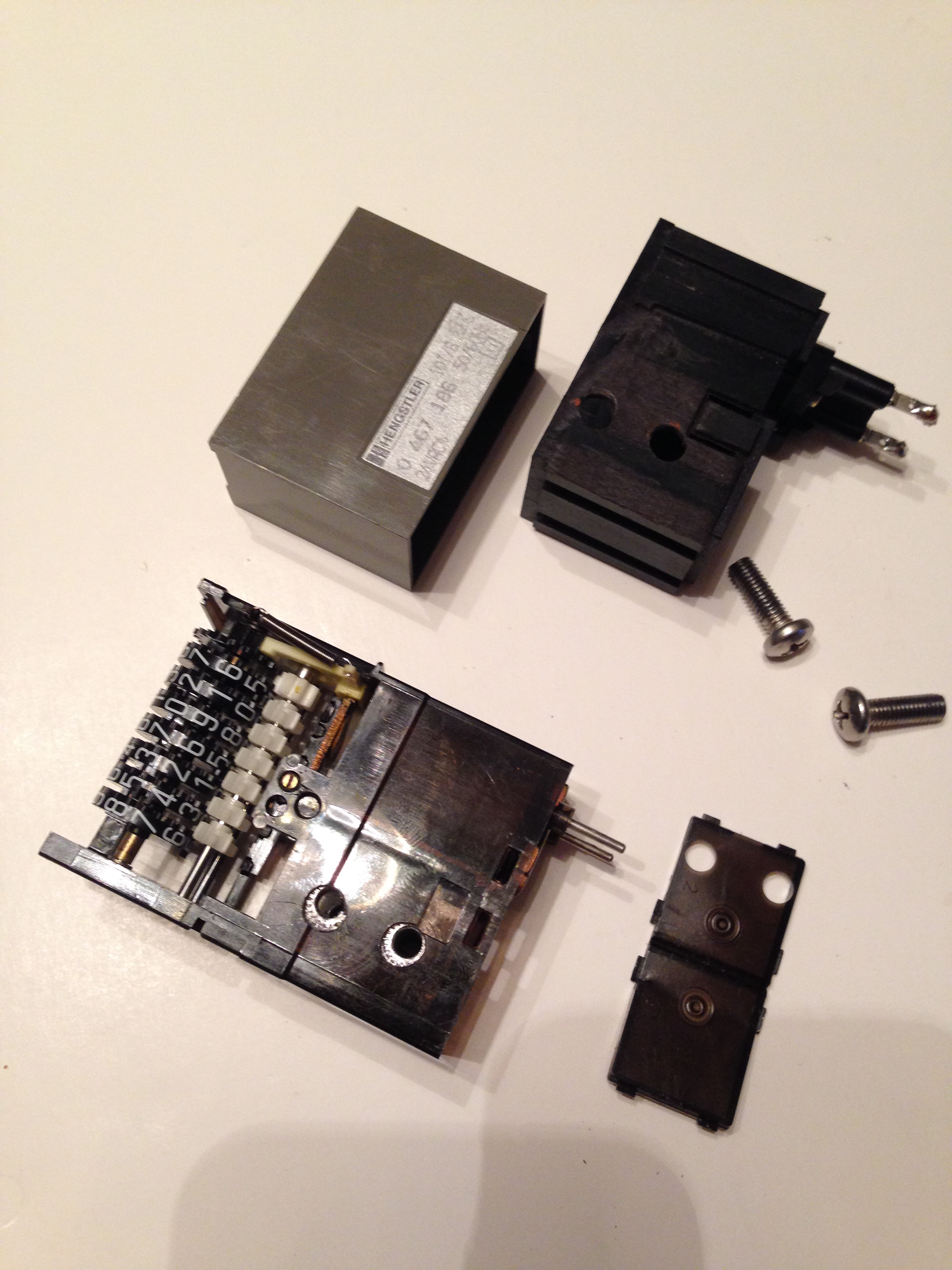
 Here's the end cap going back on. Basically you just need to line up your holes to the new threaded areas. You're now digging through the inner casing and the outer casing and the counter bracket.
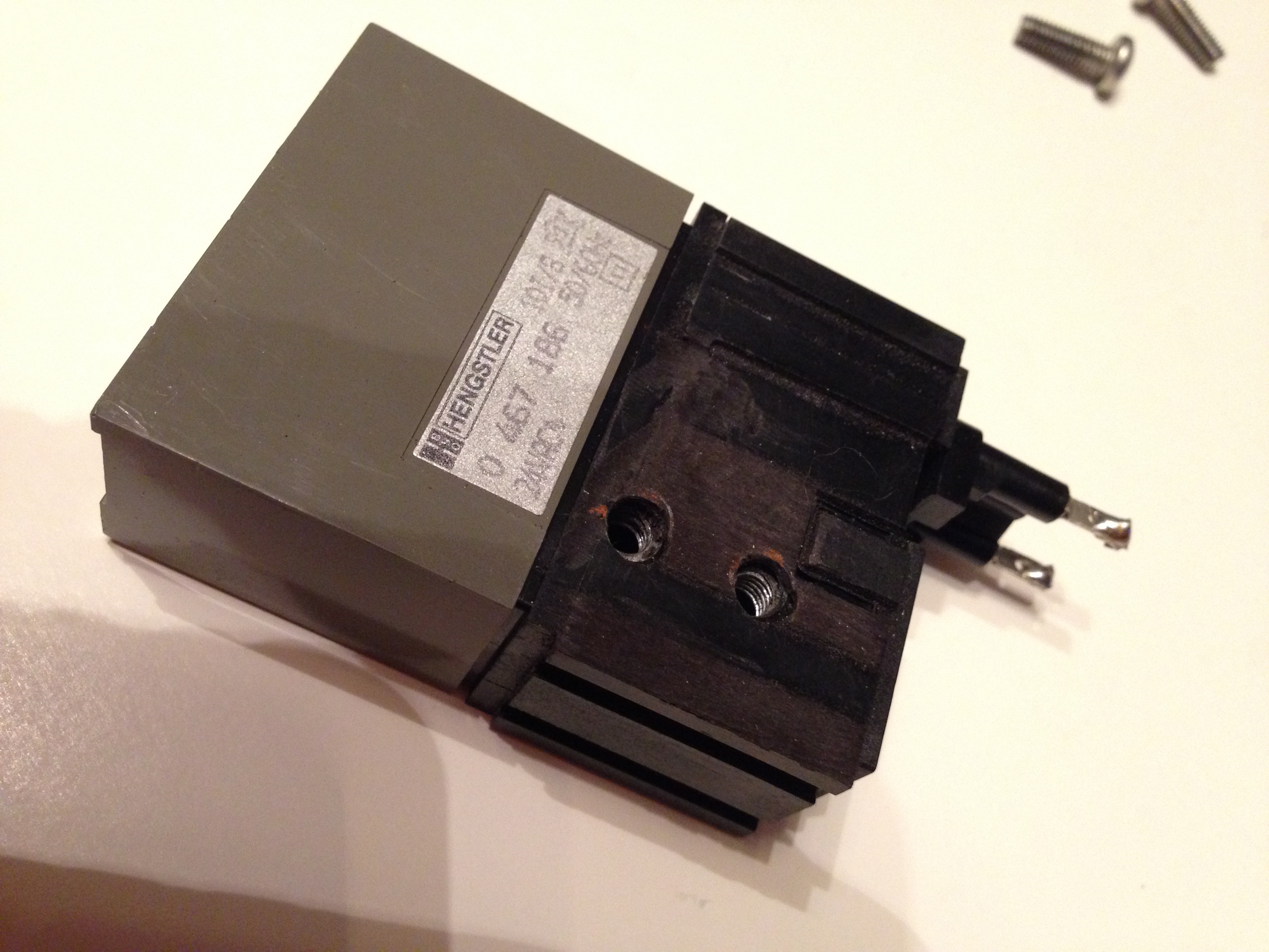 With a little help of a dremel, all the holes lined up.
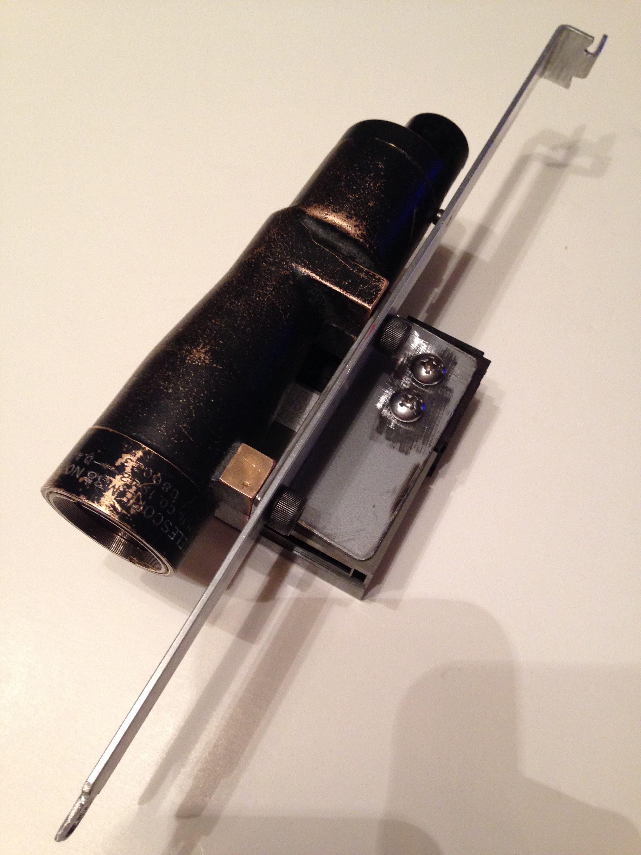 The screws sandwich all the plastic components of the counter and go through the bracket and hold very securely.
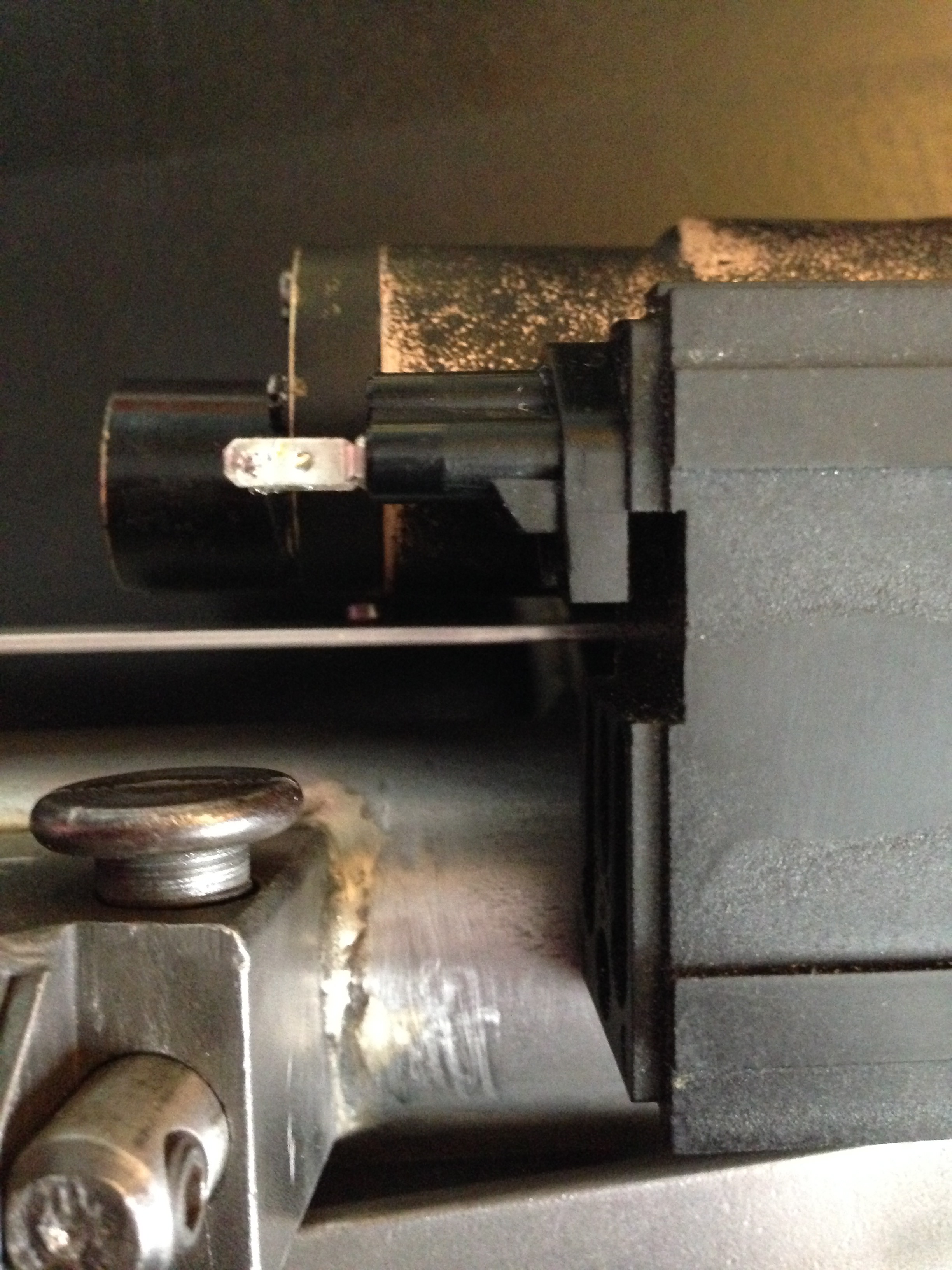
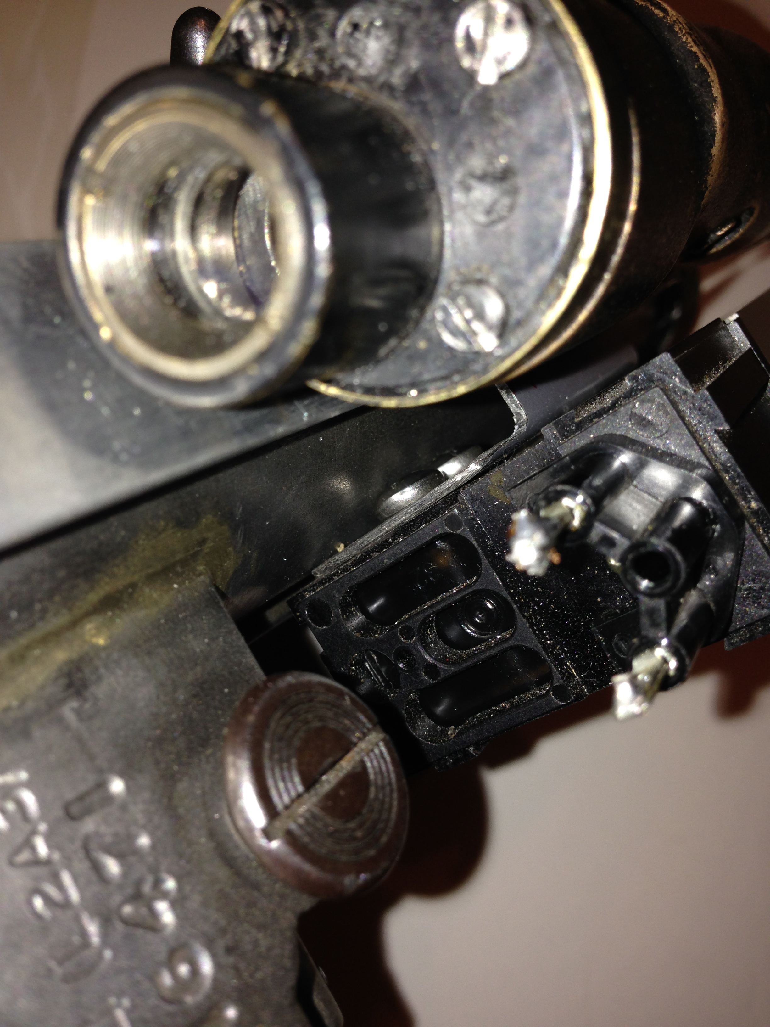 With the scope mounted, the screws fall in a great place that are difficult to detect. I'm going out of my way to shove my phone camera lens down in the nooks to take these pics.
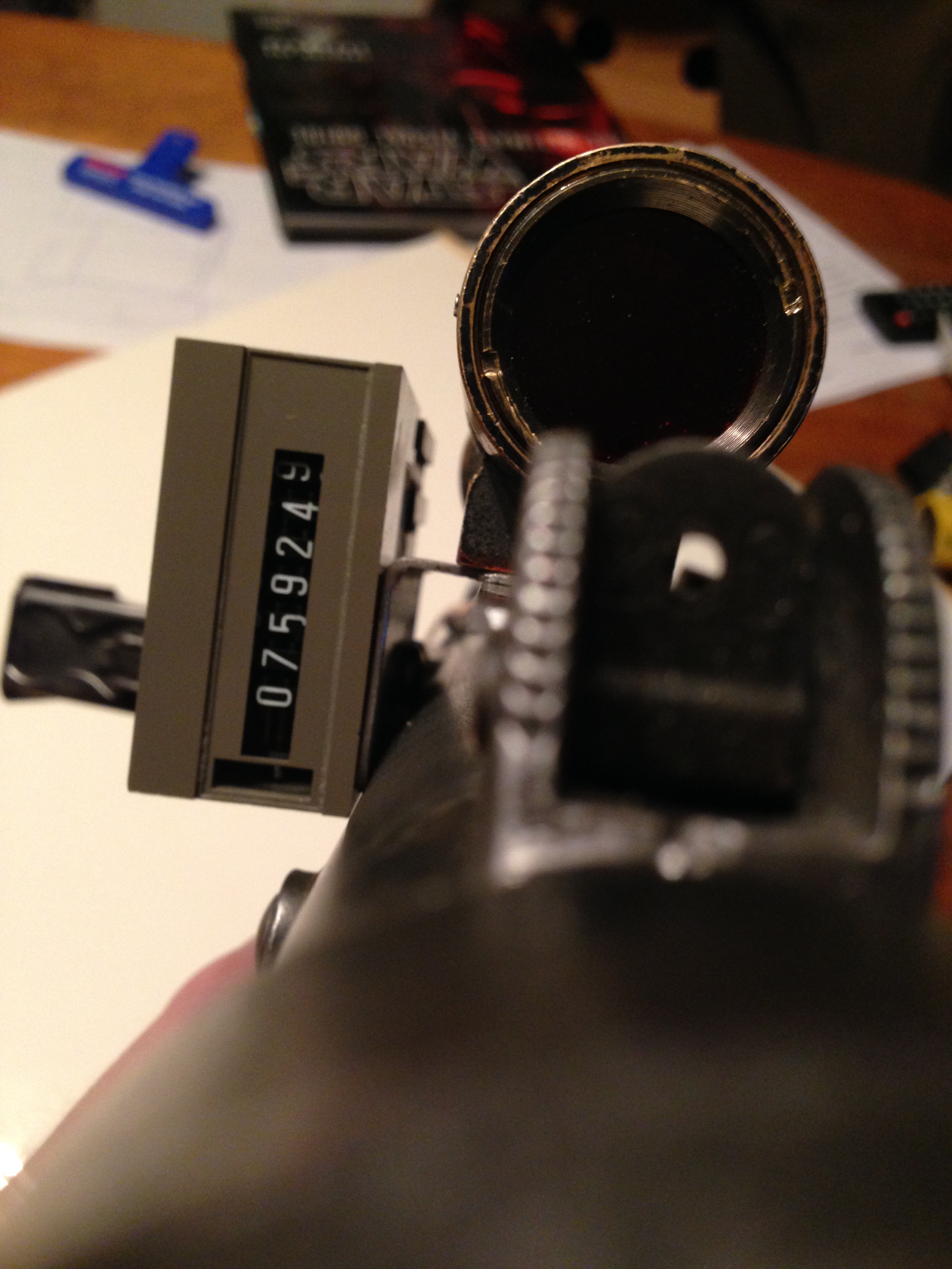 The screws are almost invisible from the rear end as it hugs nicely to the receiver tube.
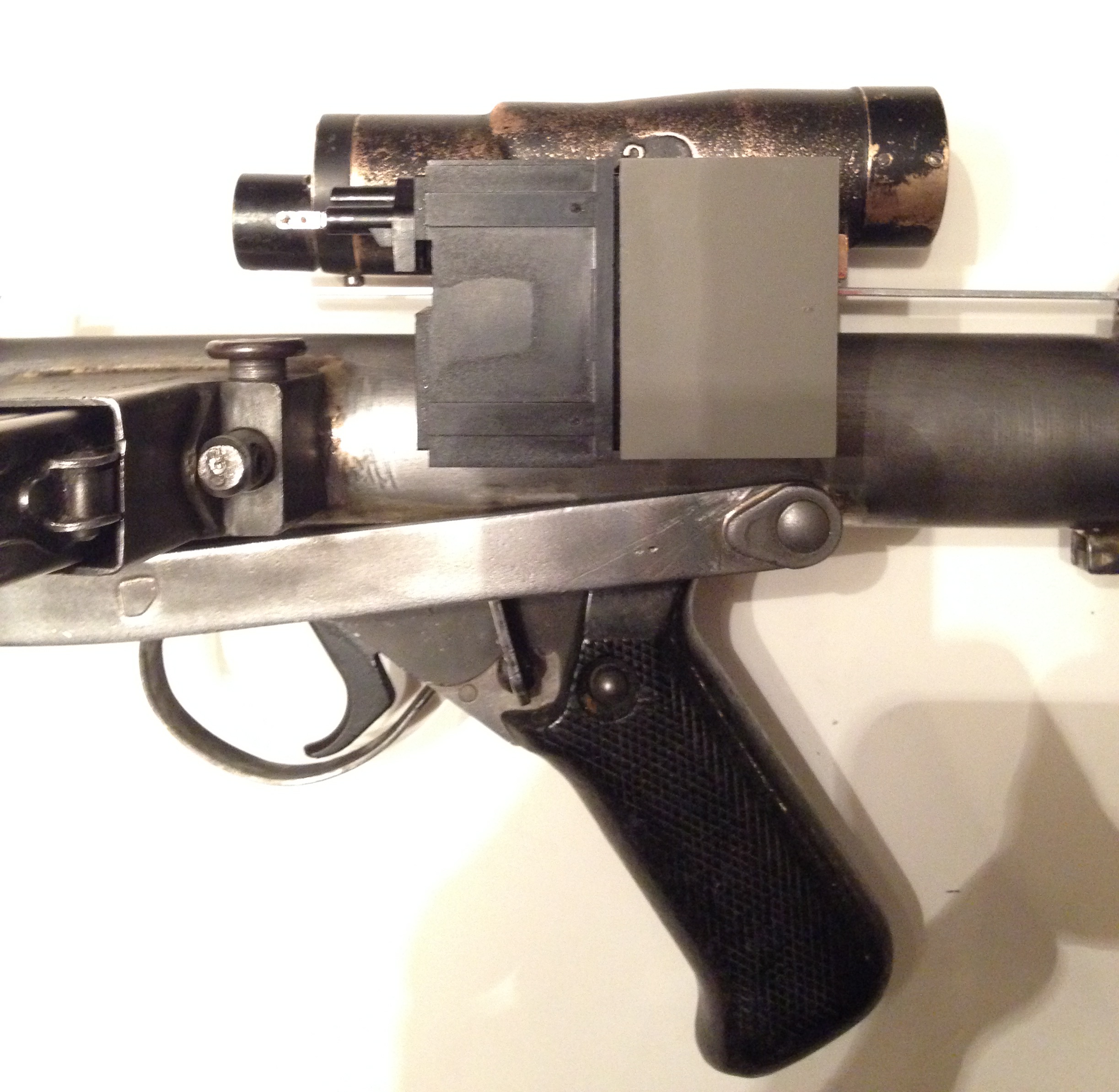 If I'm not mistaken, the counter is sitting in the agreed upon correct spot? right?!!?
 -
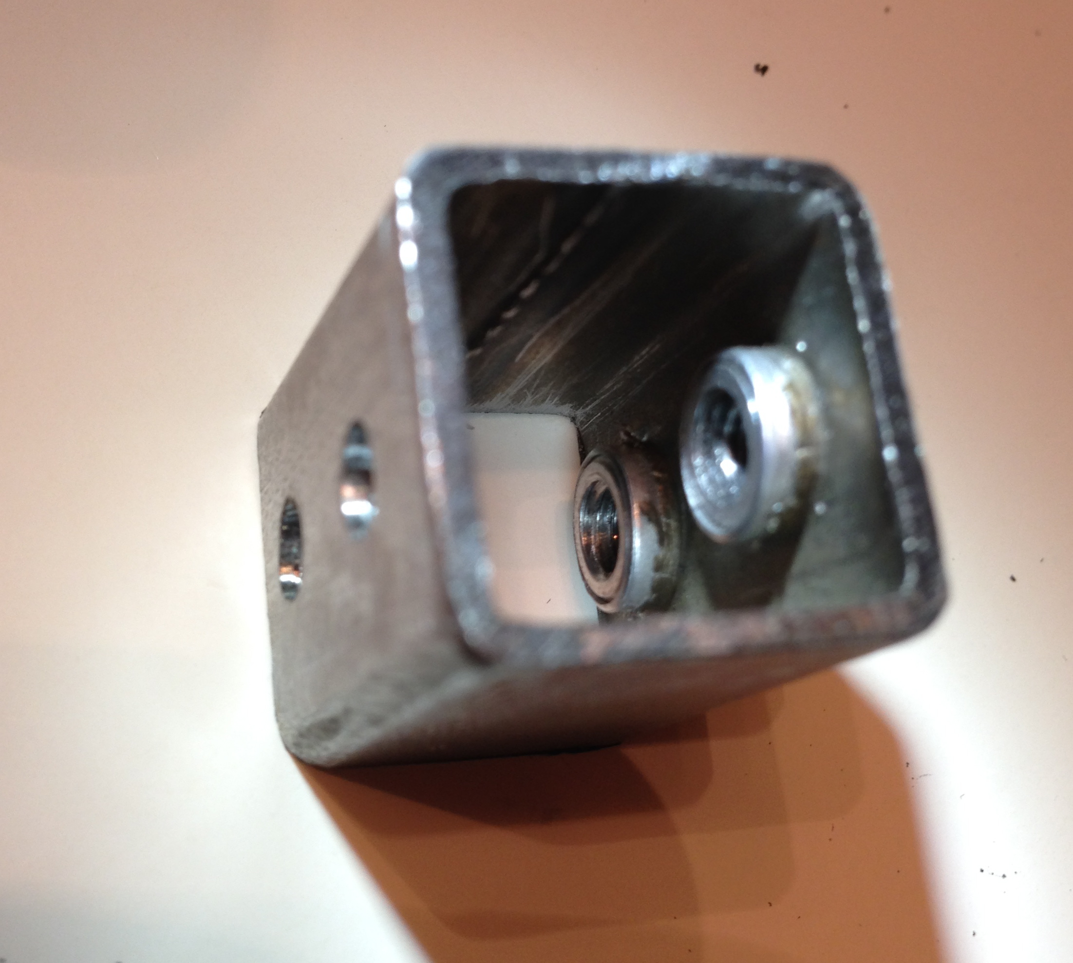
Well, I had a strike out on finding a hengstler counter locally. In fact, it's a real bummer as the shop that I'd mentioned in the last post completely sold all of their stock at auction; we're talking three warehouses the size of a Home Depot each of floor to ceiling industrial salvage! It's a true bummer as this was a honey hole of industrial equipment with machines dating back to the turn of the century. So with a total bust, I'm going to have to make the counter work that I have.
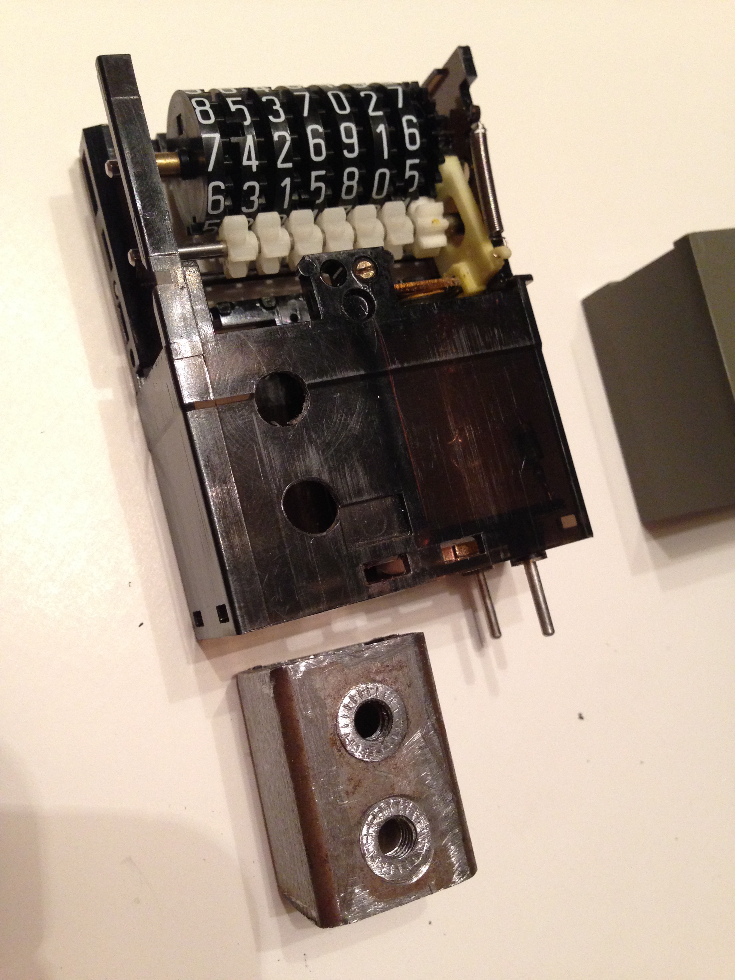
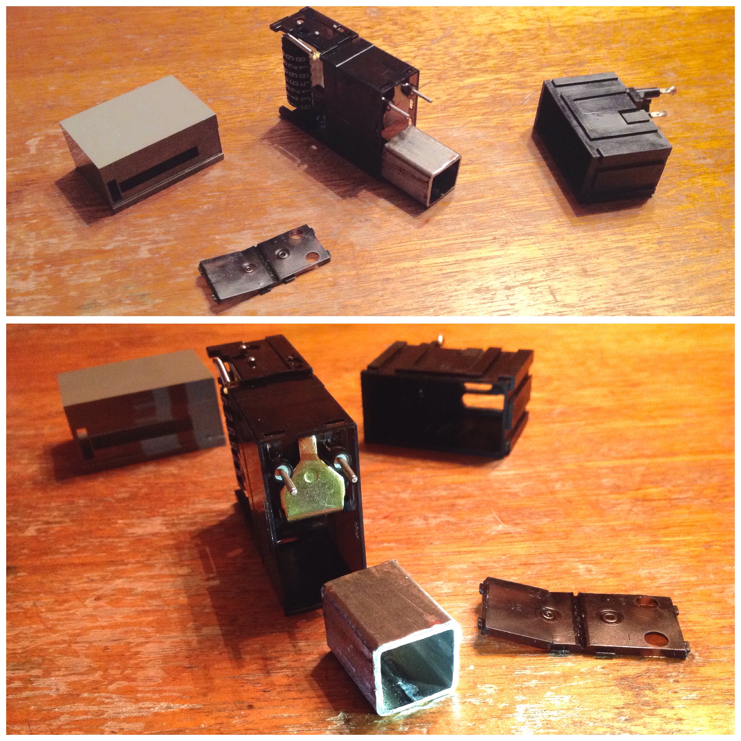 Since i knew there was a blank space in my counter thanks to the see-through area, it was just a challenge of figuring out what to fill it with. I removed a cover plate a little less gracefully than I'd hope for, but found that the inside area is 3/4"x 3/4" and I dug through my scrap steel and found a piece of square tube of those dimensions. It slides right in place and this will be easy enough to drill and tap and give me a really nice surface to mate with. It will just sandwich the all the plastic parts together in between which I'll likely use some epoxy to hold tight as well. I'm happy because I just want to get everything mocked up as i'll likely make an entirely new. all-in-one scope rail and counter holder out of steel down the road, so I wanted this removable.I know it probably doesn't look like much to most folks here, but this had me puzzled for a while now. I'm pleased.
 -
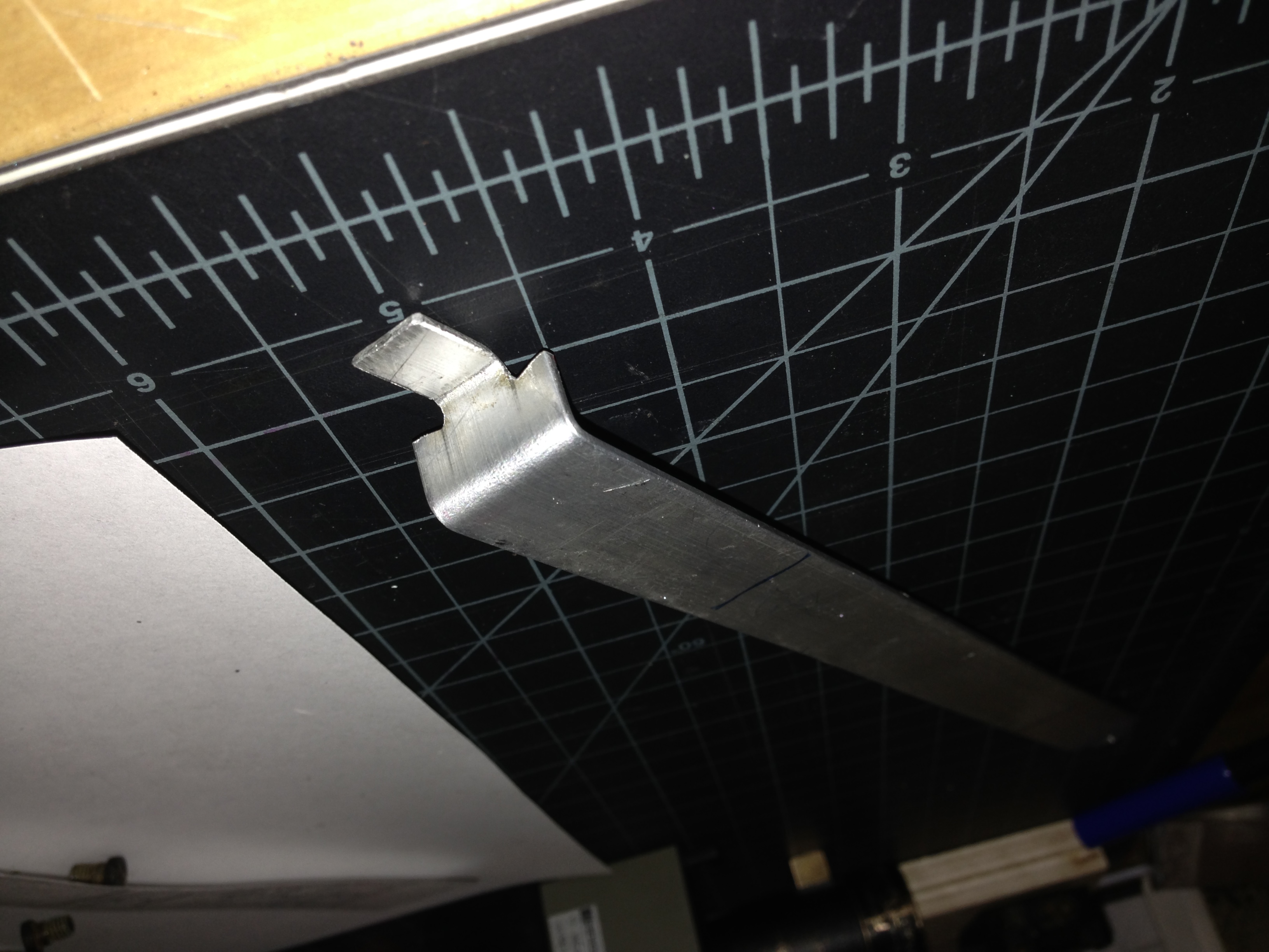
Thanks Ian for the inspiration. I checked out your current build and it looks like we are pretty close as far as where we are at (though you are a little further along)
[ Since I had the identical leftover brackets from Ikea, I figured I'd just chop mine up for fun to see how this idea worked.
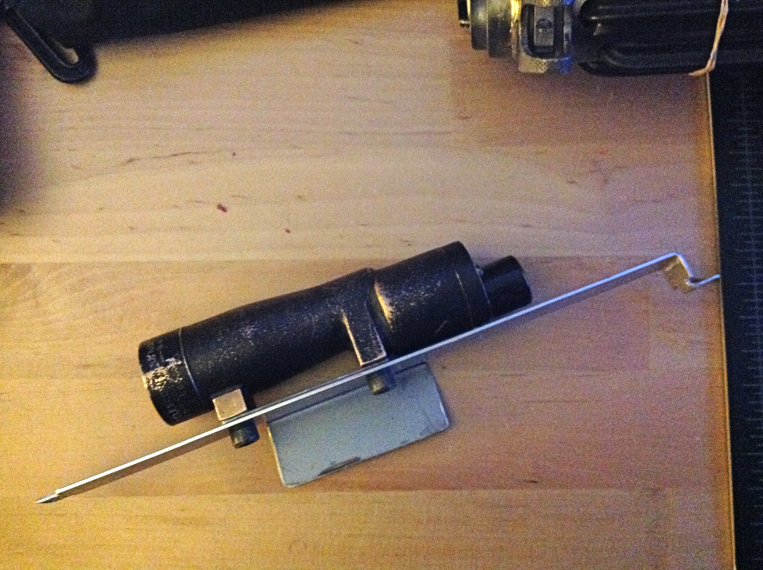 It actually worked out pretty nicely!
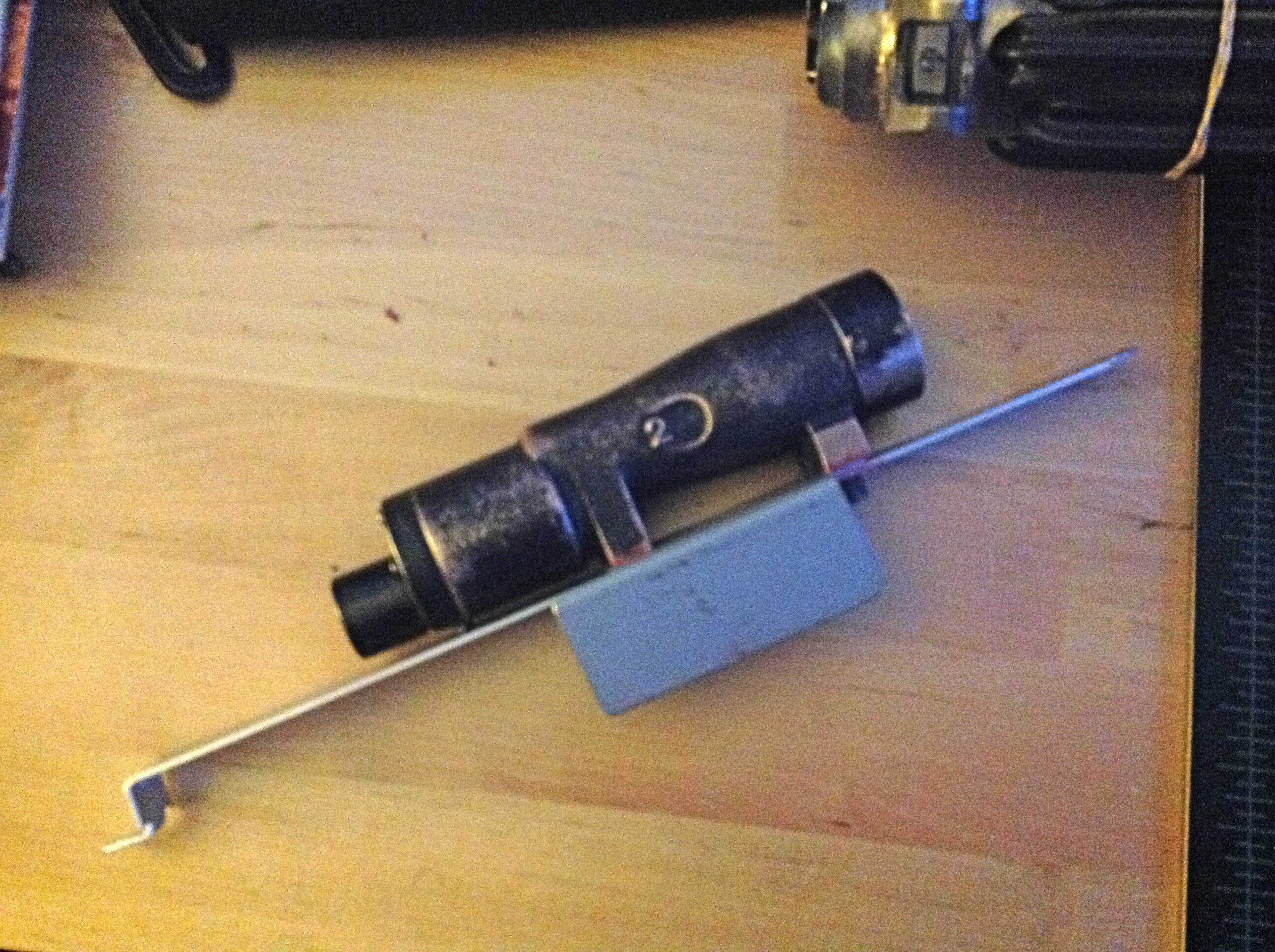 And saved me a trip to the hardware store!
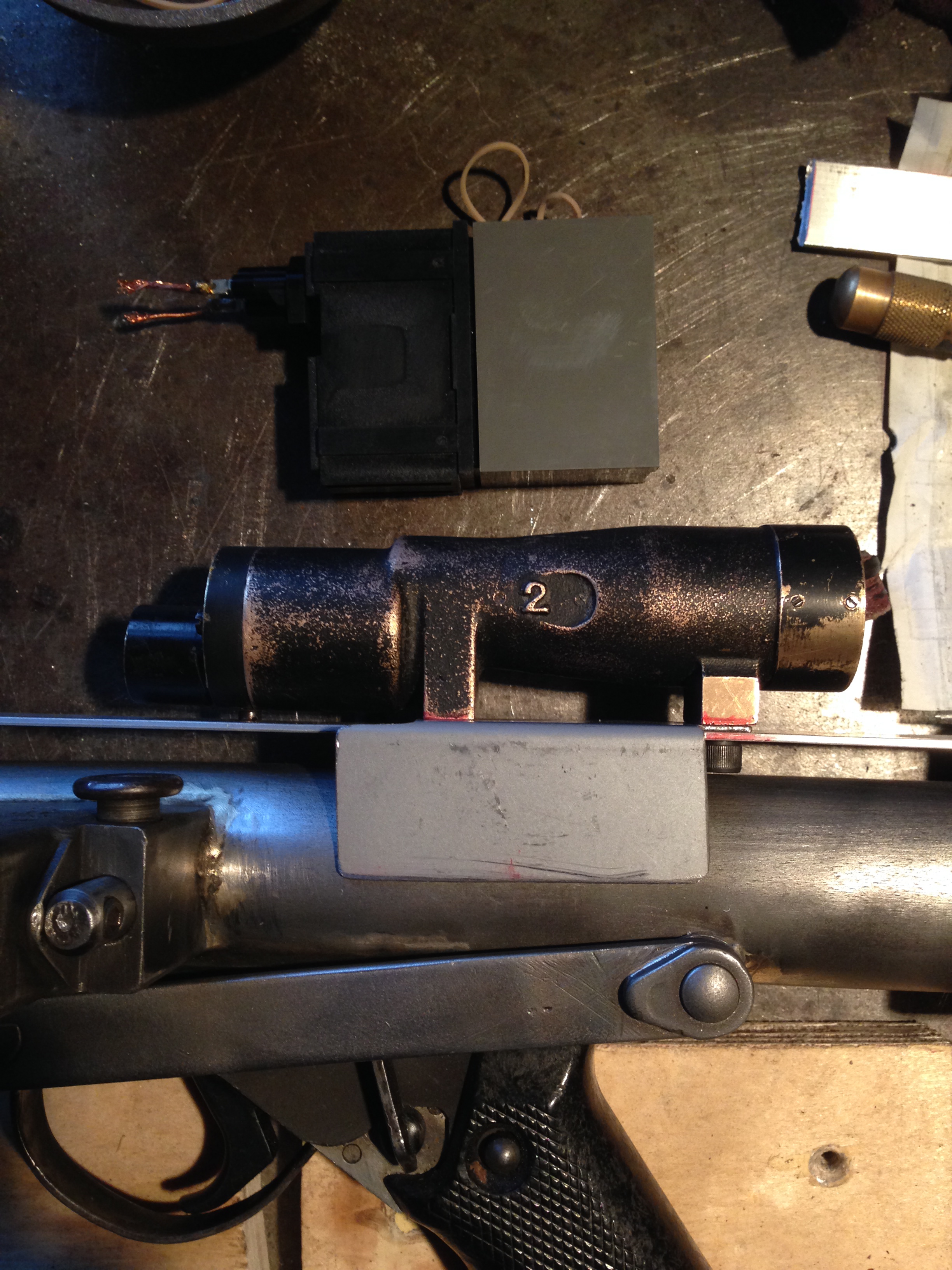 Mine will sit down. I noticed some people have theirs face upward to attach the counter to the bracket. With this ikea treasure, it actually sits just flush with the receiver tube which is nice.
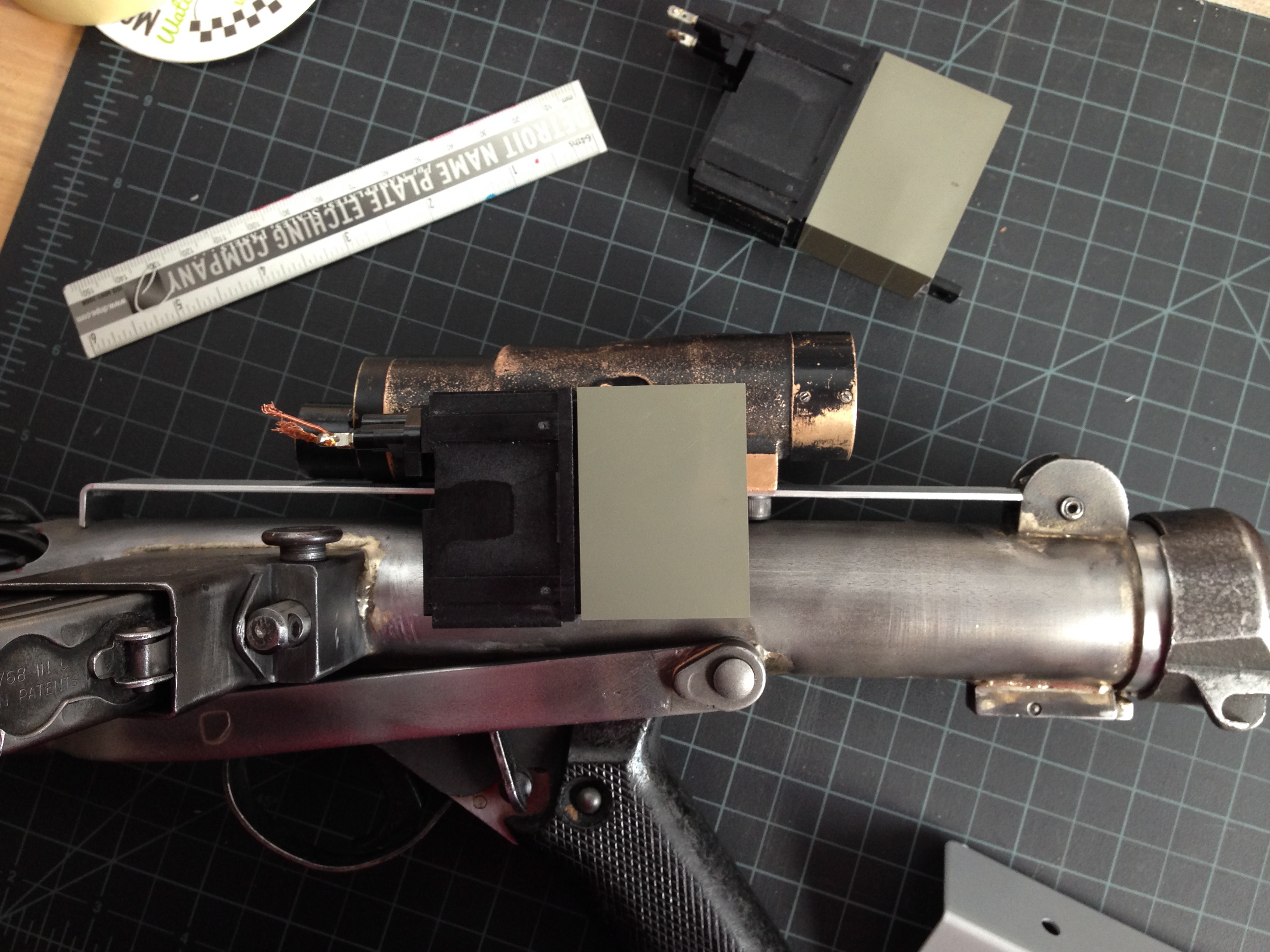 I haven't attached it yet as I'm still trying to figure out how I'm going to do it.
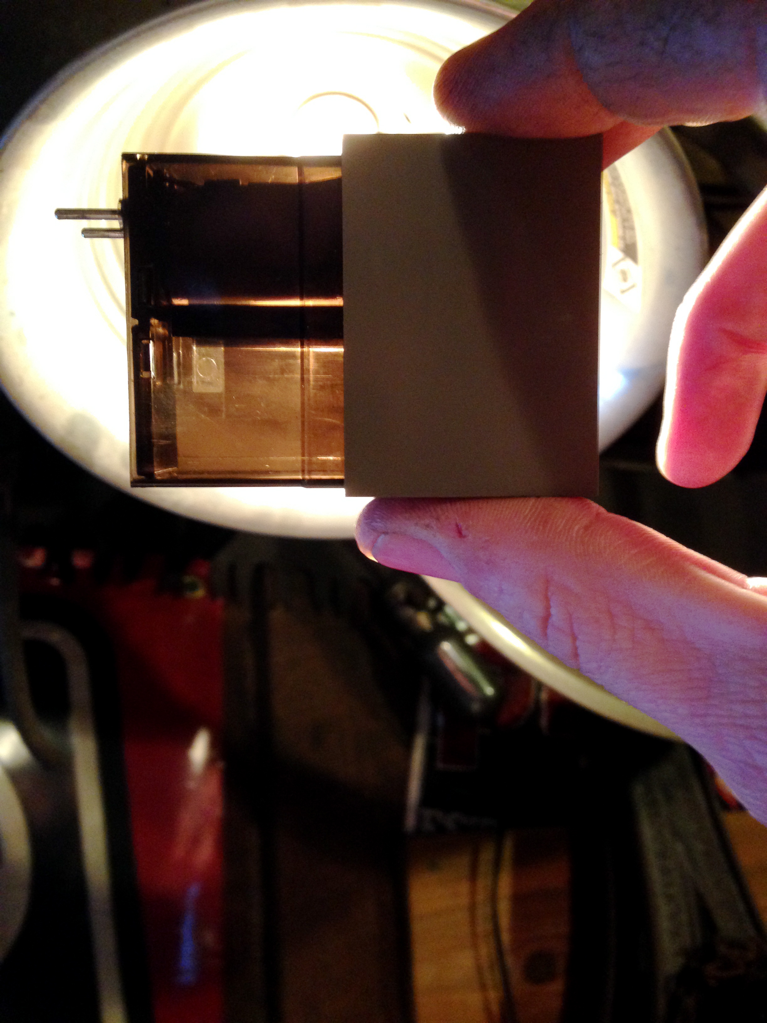 This is what mine looks like without the outer casing on it. it's a dark acrylic piece with not much to dig a screw into for a meaty bond. This is why I'm a little hesitant to just screw it on. I was thinking about perhaps drilling a hole in the see-through area and maybe trying to fill it with resin or caulk or something that will give me something solid to hold a screw in. It's been so cold here the last few days I've been nervous to go out to the workshop and attempt to drill as I feel it may crack or shatter,Anyone else using on of these they can lend advice on attaching?The other thought is I may (and this is a big maybe) have a lead on a local place here that could possibly have some of these sitting around. I'm hoping to find an older one with the proper logo, but I'll take what I can get even if it has a metal piece to screw into, it would be better than this one I have (I think)What are the Eagle logo Hengstlers going for? What's a fair price on them? This place I'm planning on hitting is has a lot of large scale older machines that they try and sell all together but there are some of a pick and pull drawers/bins/tubs of an industrial equipment and has a lot of older stuff so there's a chance they may have one *fingers crossed*
-
1
-
-
I wondered where I got it from. I reckon it is a bracket from a bed I built recently. You always have parts left over on these flat packs don't you
I happened to have the identical left over bracket that I cut up to do the exact same thing today

-
I had some steel angle so drew up a design
I think I have two chunks of the same angle from ikea
-
1
-
-
I'd love to see some pictures
-
Spectacular job with the Roy track. Great stuff at a fair price!
Have you considered making a one-piece counter/scope rail? Those look cleaner to me.
Otherwise, I would just make an "L" shaped bracket like others have done to mount the scope.
It's been awhile since I read your whole thread - do you have a real counter or a resin counter?
If it's real, make your bracket so you can run bolts and nuts through the metal frame.
If it's resin, I would use screws with big threads - like the smallest lag screw you can find.
Maybe smear some E-6000 between the counter and the bracket as insurance.
Your 5 year old will have some muscles playing with this...mine is well over 10 pounds, closer to 15.
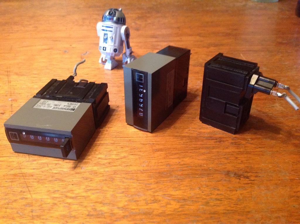
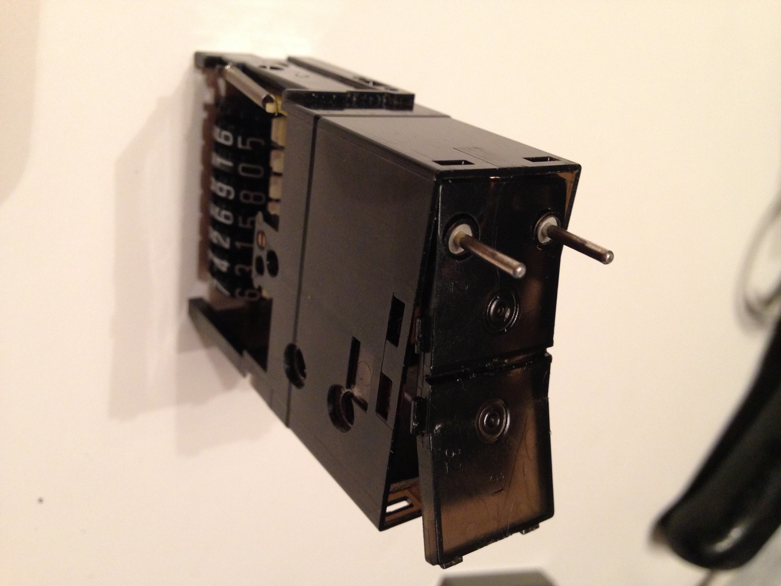
This is it, or rather both of them. They are "real" but not the metal frame kind. I believe they are a 404 with the more modern H logo. All the internal parts are plastic.
-
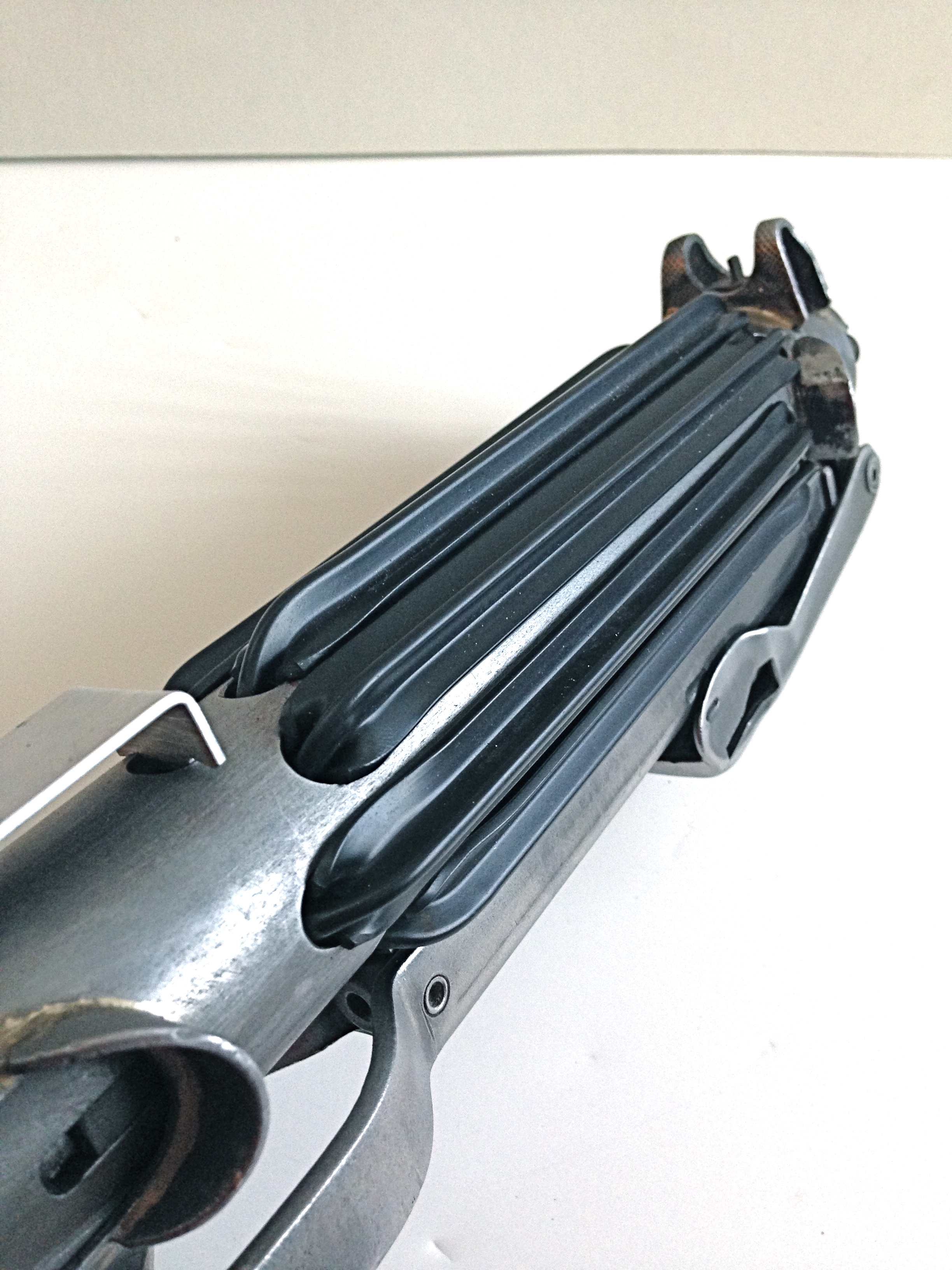
It's been a little while but I didn't have too much to do until the t-track showed up. I got my package from Roy which luckily all the tracks made it since the package was opened and simply stapled shut on one end… scary I almost lost it!
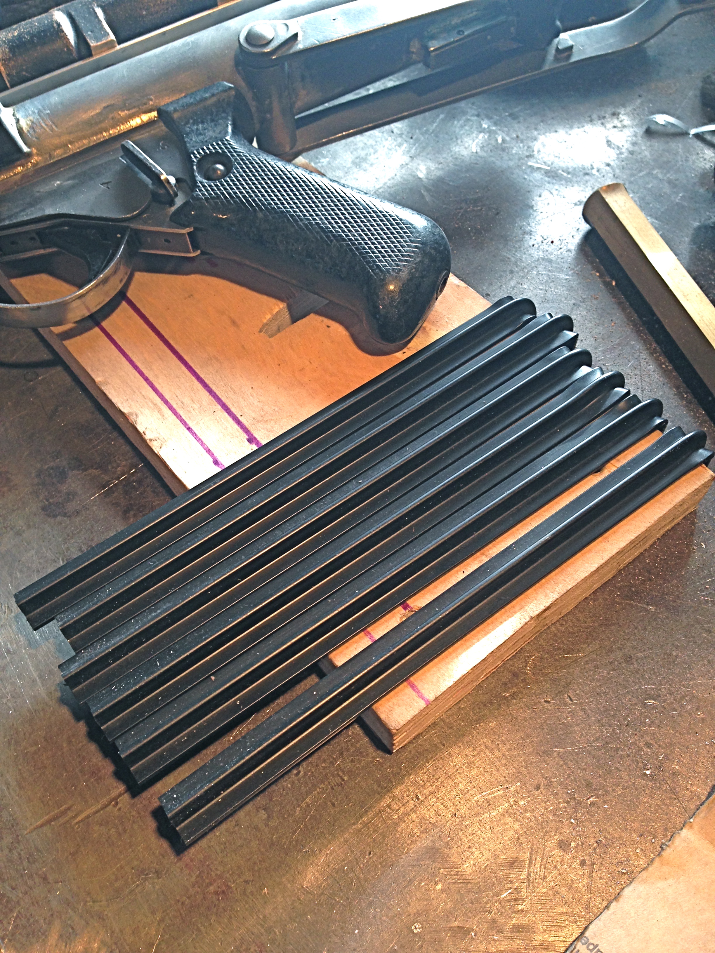 The first step was to drill a 1/2" hole in my scrap wood to be able to make the first sided bend. The scrap wood was about 3/4" thick and knowing I would have some to trim I felt it was okay to use this depth for the first bend. I bent all 6
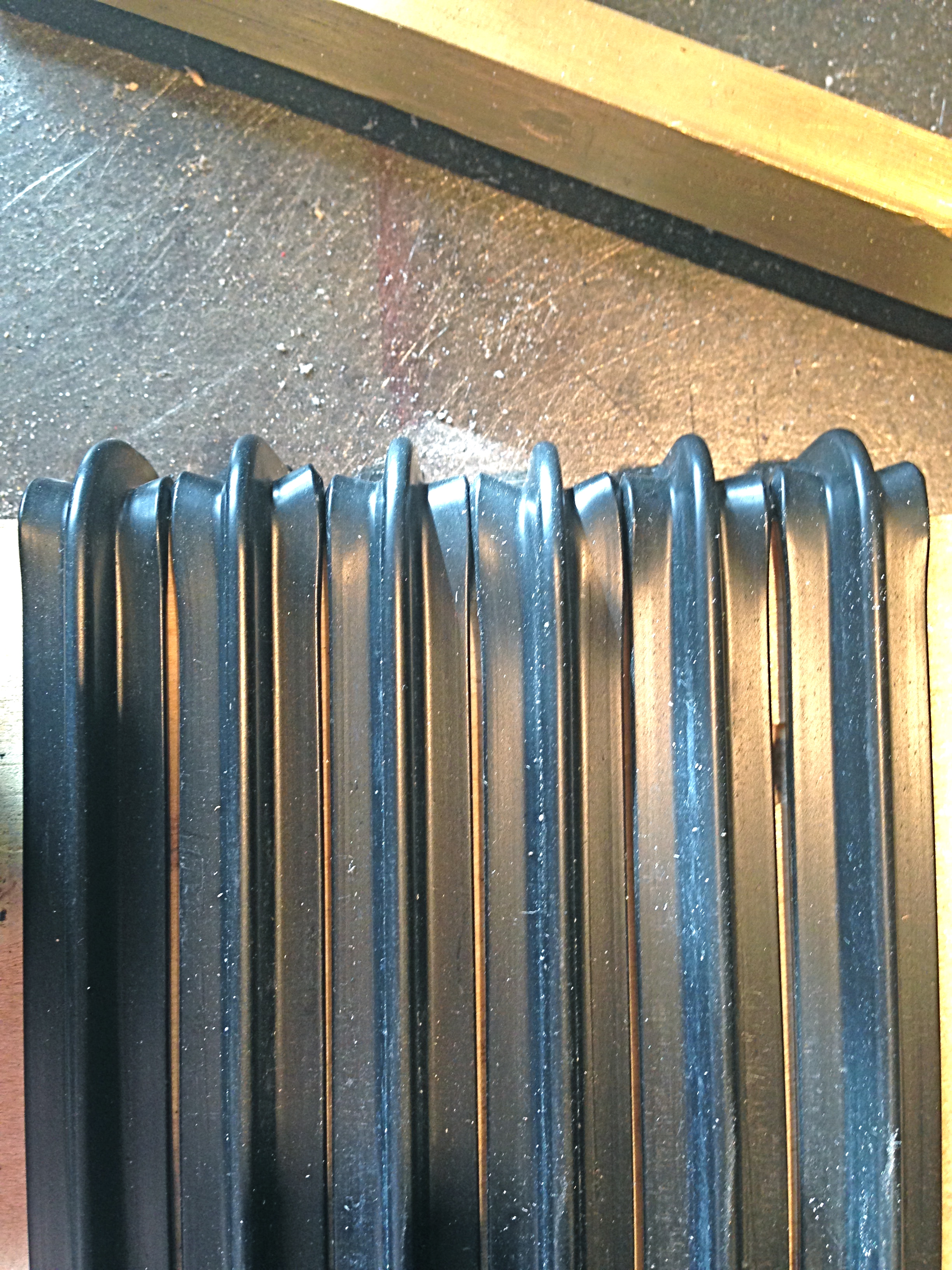 Bend 1
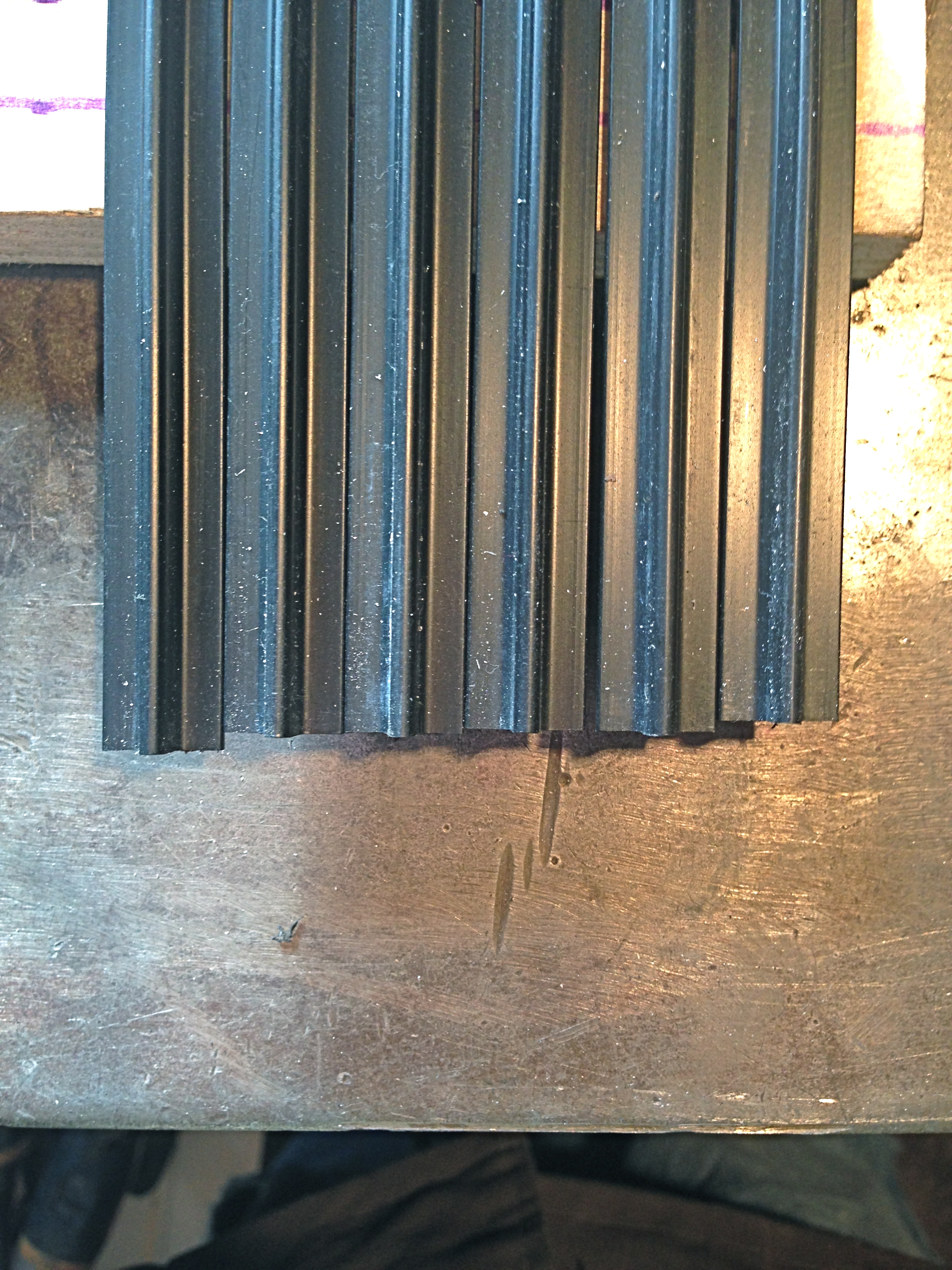 Like others have mentioned, this stuff heats up FAST!!! the thing I didn't think about was stretching and as you can see I ended up with different lengths. All the ends needed to be trimmed so it wasn't a big deal, but just thought I'd mention it since it happened to me.
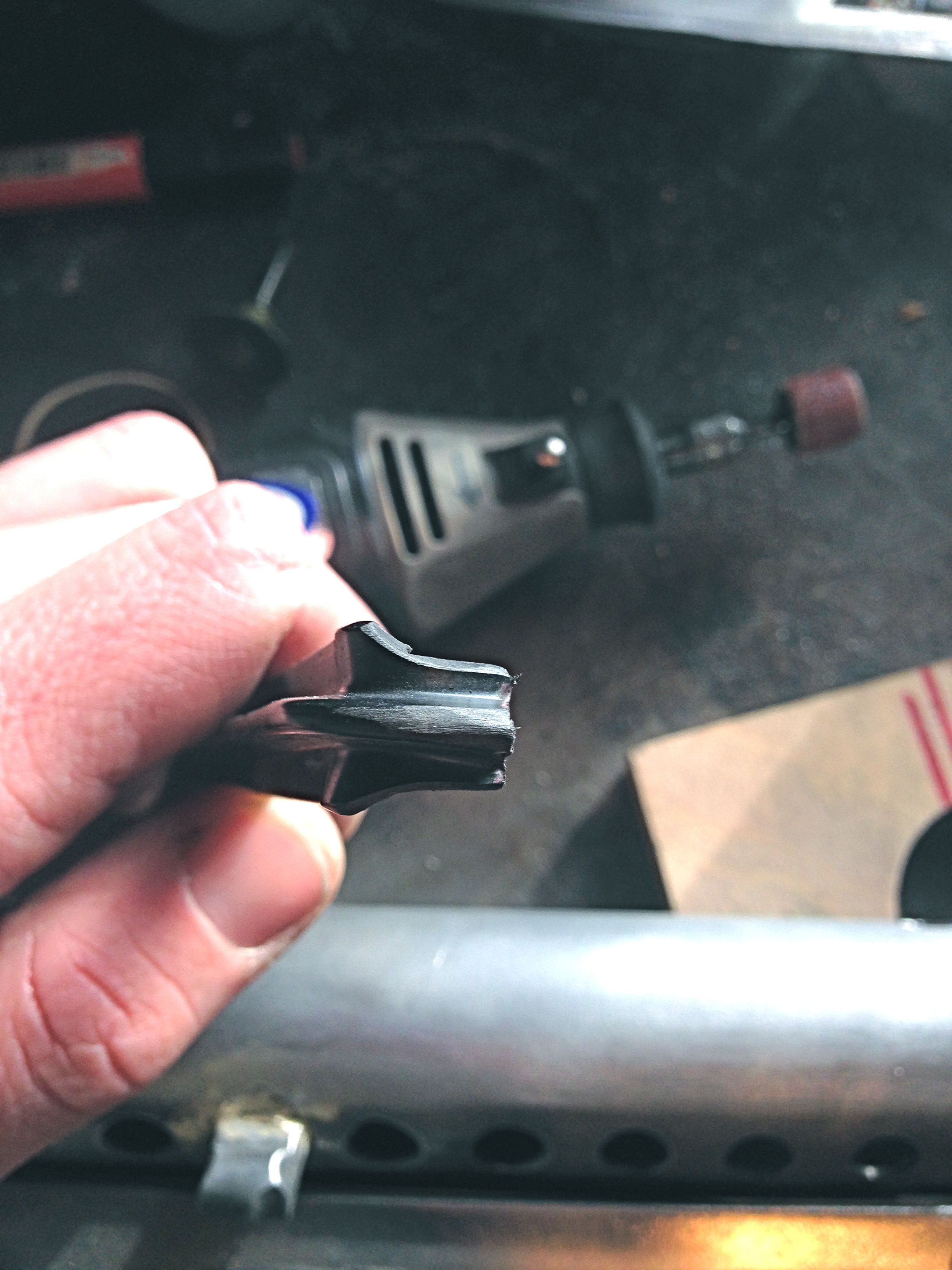 I didn't drill my holes up to 1/2". I think I topped out at 3/8" so would have a tighter hole. (that's what she… nevermind)So I had a bit more shaping to do.
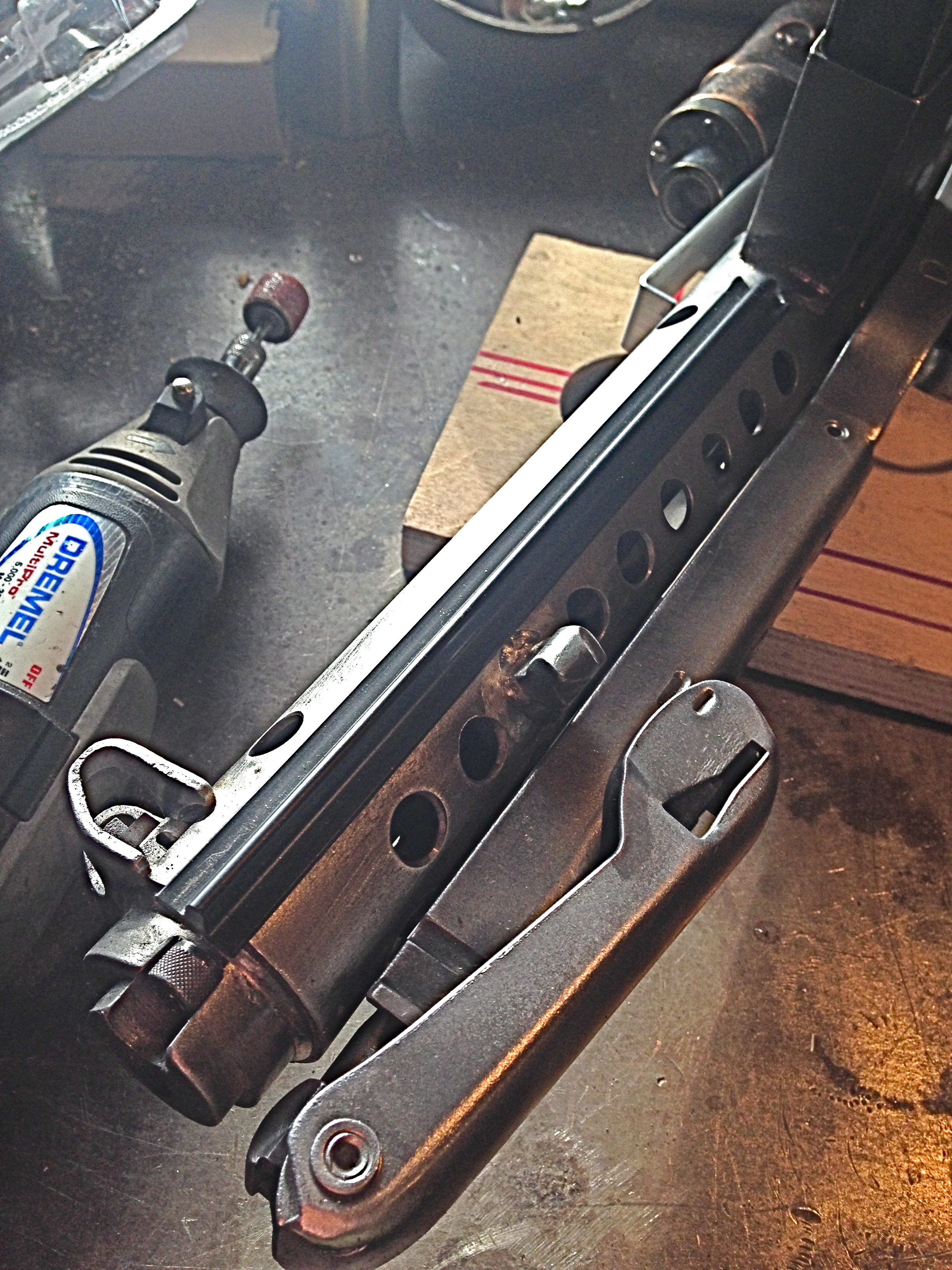 I started with the holes above the bayonet lug as they are a longer set to go between, and perhaps the least visible.
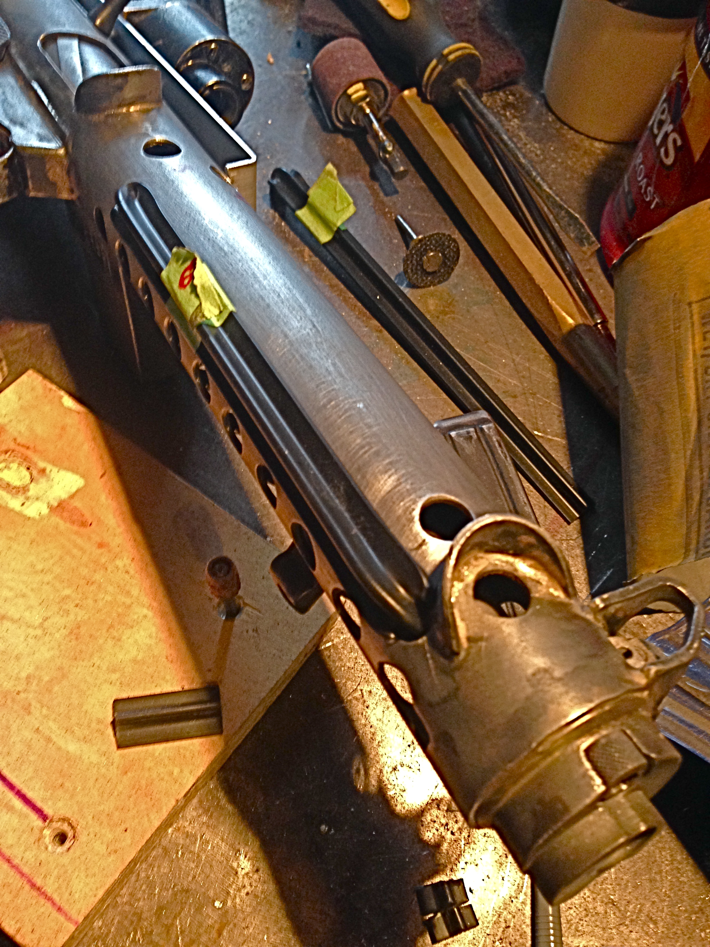 Then I jumped to the opposite side to do the other lower. The tape on these register with the sets of holes I wrote on the receiver tube so I didn't make the same one twice.
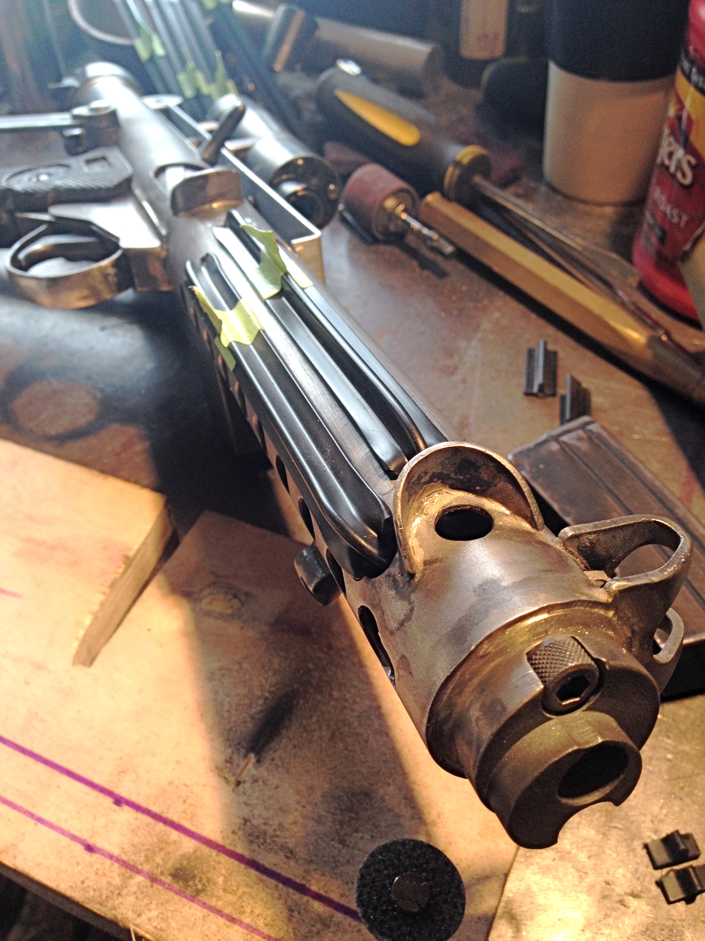 One by one I just heated up the opposite end after cutting it down close to length I needed and making the same shape in the track so it would fit my receiver holes. This went really quick!
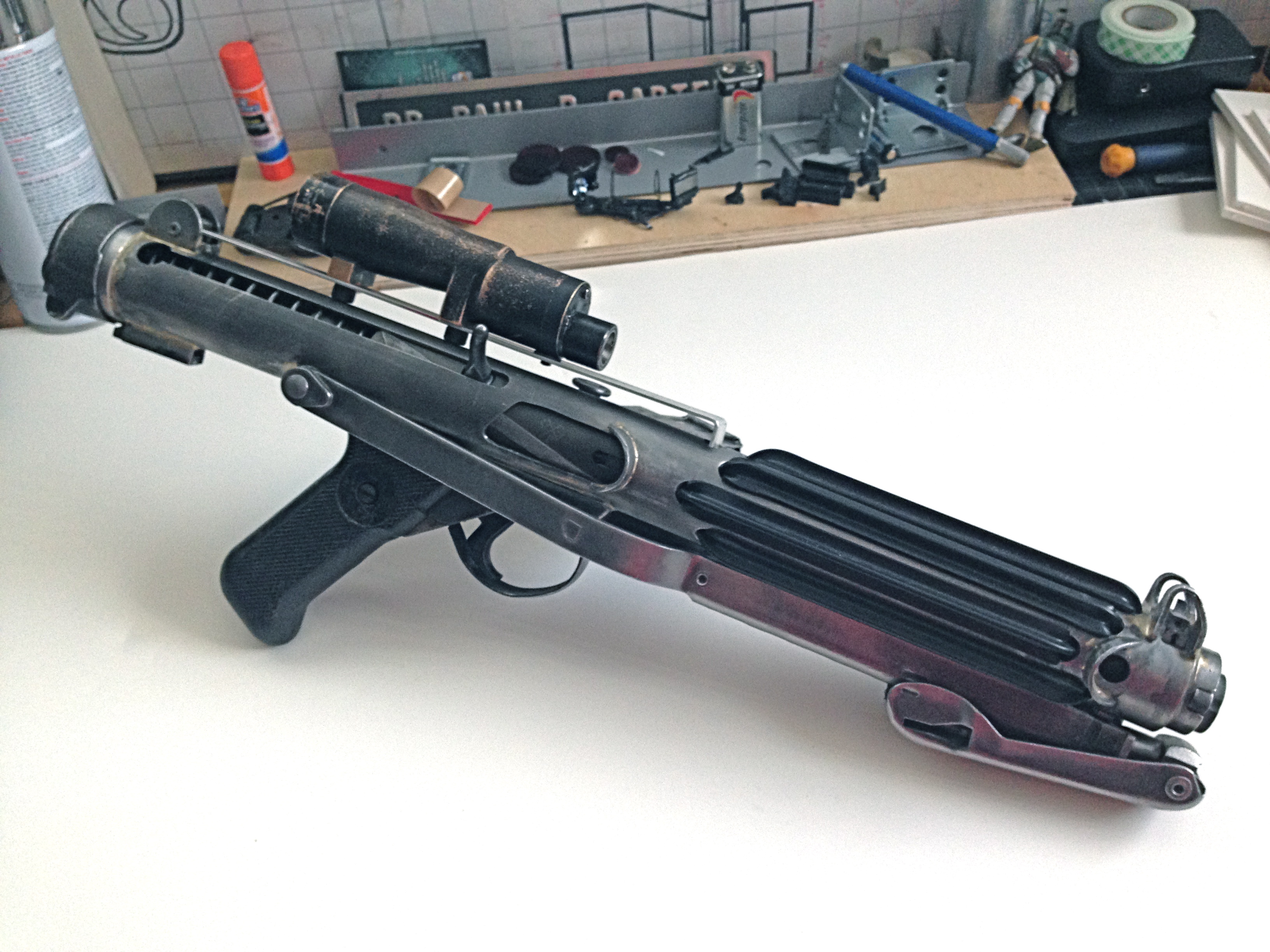 I worked side to side and ended up on top as I was hoping to have my technique down for the most visible fin.
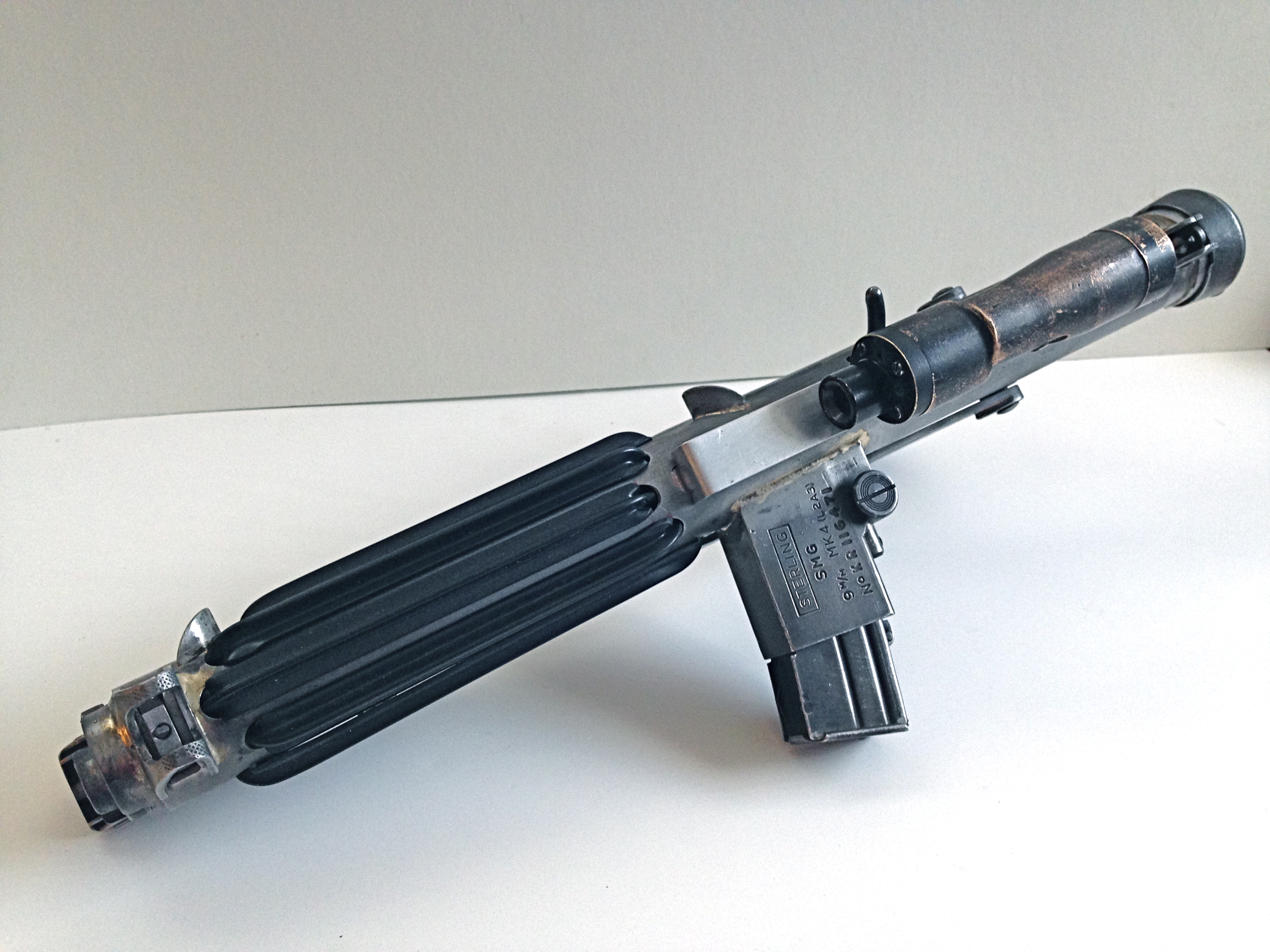
 Now I just need to find a good way to mount my counter. Mine being an all plastic version, I'm a little nervous about just driving screws into it and it will hold. I know the originals were glued and that's why they rarely show up on screen. With a 5 year old who can't wait to play with this gently, I need a solid way that won't just break it. Suggestions?
-
1
-
-
Looking fantastic Kev. What thickness is your scope rail? It is Aluminium?
That's 16 gauge so roughly 1/16" thick by 3/4" wide and yes, aluminum, though I may remake it from steel as I know those two don't play well together over time. I guess I'll also have that issue with the brass and steel too though.
-
1
-
-
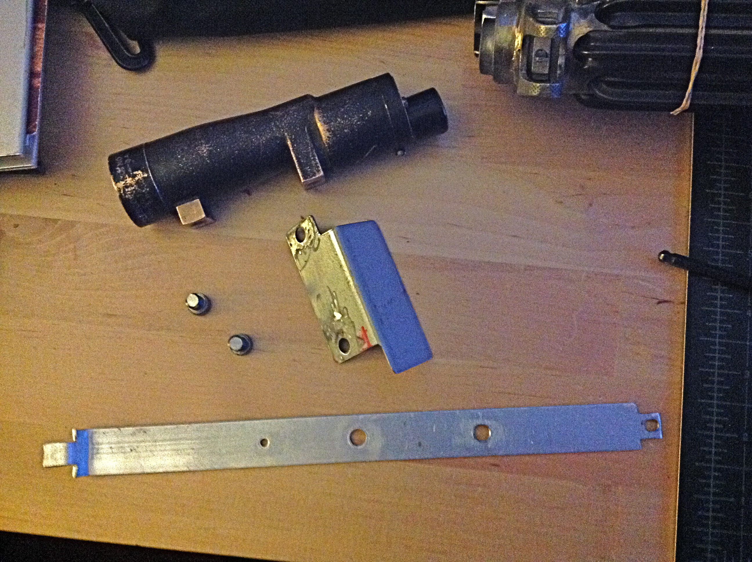
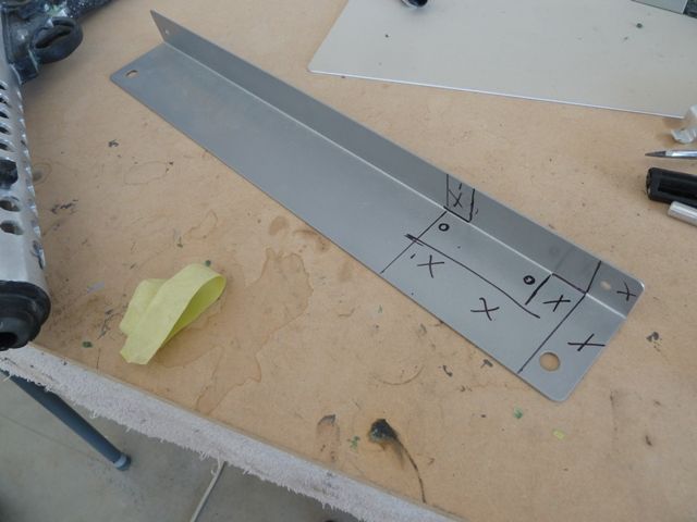
EDIT: I don't get why some of these photos are showing up, upside down! They look correct in my photo editor and when I post them to Flickr… sorry.90% of the time, I think and plan ahead. For that 10% left of things I don't think of or plot for, it eats 50% of the total build time.Case in point: Scope Rail:
 Because there are so many threads on how to build these guys, I'm not going to go over again and again how to make it. In one part you just need to build it to the specs of your blaster as they all are going to vary from one to the next. I started off with exact dimensions of another post and found out I was short, so this was #2.
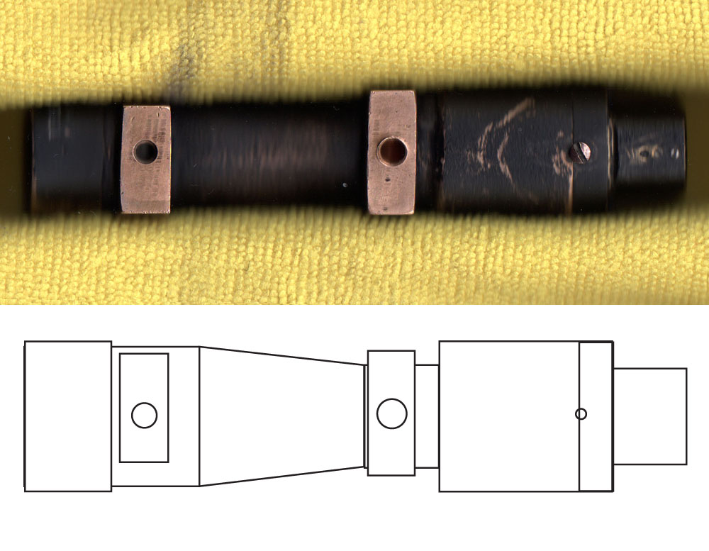 Mounting the scope can be a little tricky as everyones scope, either real or resin is going to vary a certain degree. Above is my trick to this. I placed my scope on my scanner and just zapped it so I got as accurate dimensions as possible. Notice that the forward hole has been retapped so it's larger. What I did is traced the outlines of the scope and made a mirror image so I could place it on the scope rail to line up all the holes.
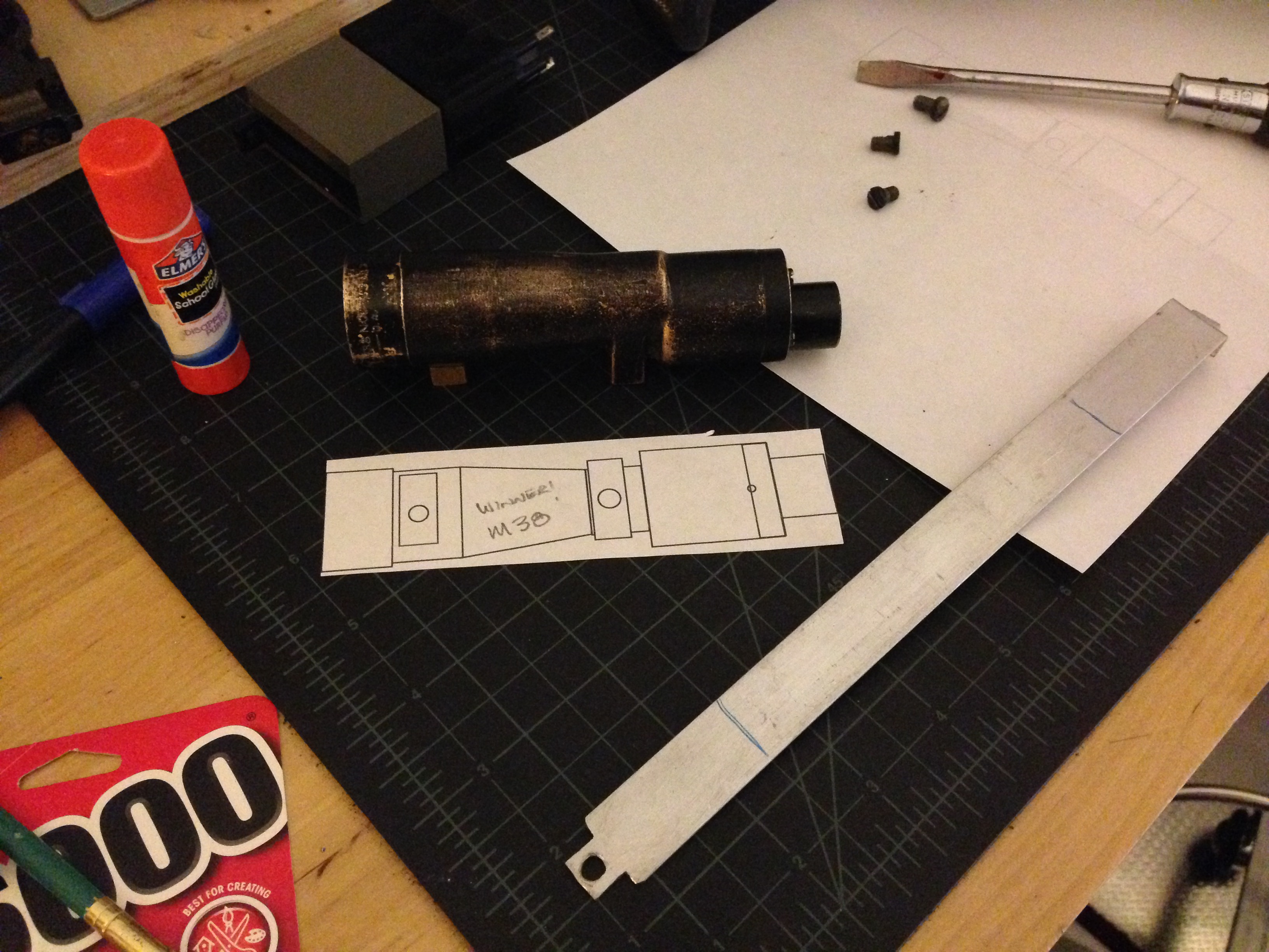 I had to print three times to get everything right. After I was happy with the alignment of things, I used some of my son's paste to stick it down roughly in the middle of the scope rail which seems to look correct on everything I've seen.
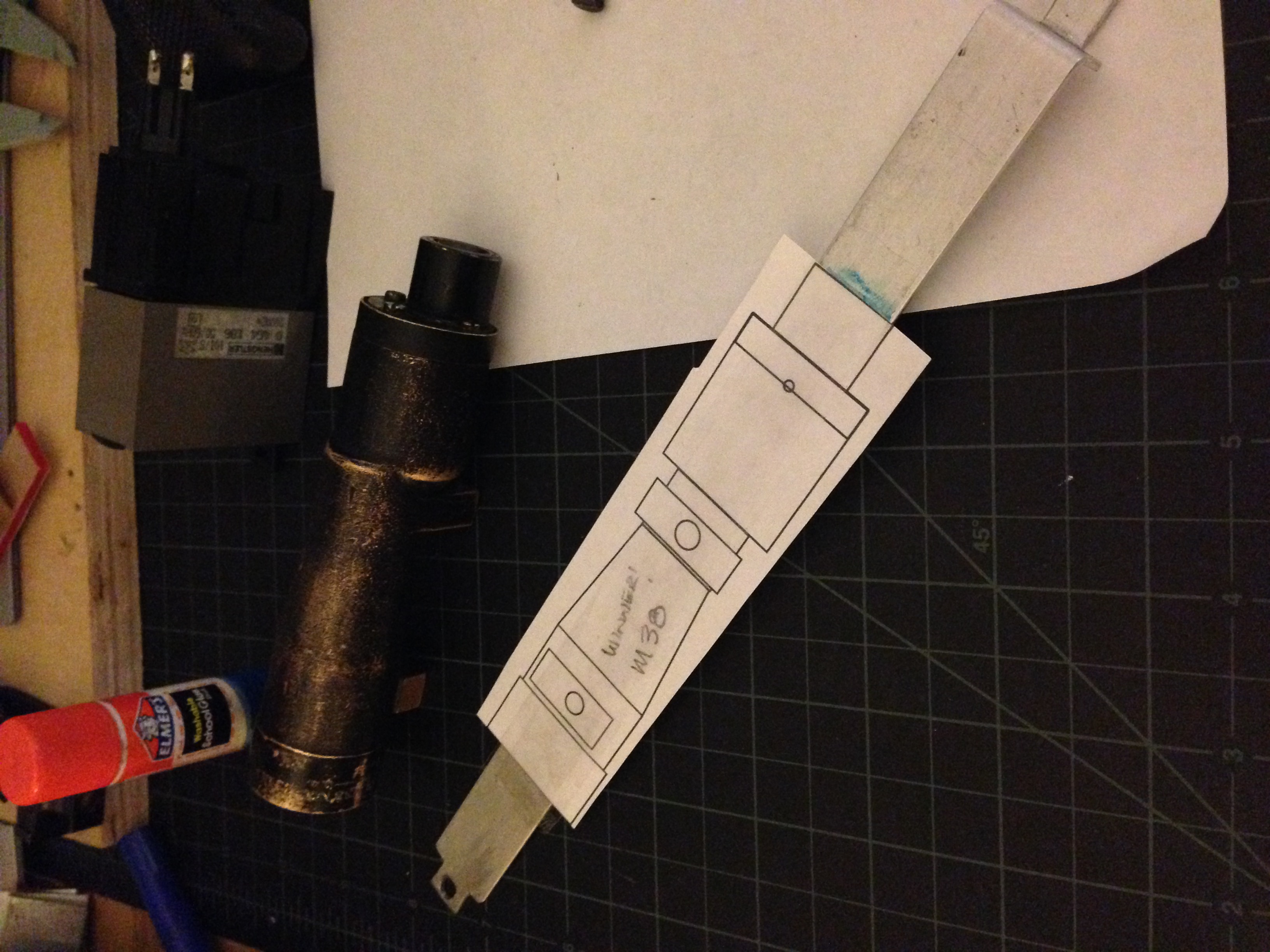 I also put a piece of clear tape over the rail as well to help it stick down.
 Drilling holes is pretty straight forward so no need to over explain that process. I did need to retap the one hole as it was stripped. So in the end I stepped them both up to 1/4" - 20. my scope also had a set screw that stuck out and hit the scope rail so I ended up running the screw through the rail as well.So what I mentioned way back when about saving myself time and not drilling out all the holes on the receiver tube, well, I missed one… I guess I got confused with different folks builds on where the scope attached at the front and where the T-track also came into play. Some folks put them both through the same hole while others use two different holes. The way I designed mine in my head they'd be in the same hole… but in reality, I needed one more hole.
 So I completely dissembled the blaster (again) and had to drill one more hole ahead of the scope rail hole. What a waste of time!
 For the rear, I tapped the site hole with a 10-32. It seems to work well, I guess you could also do a 10-24 but I didn't have that on hand. So with that treaded up and an old fillster screw from a carburetor I had sitting around, I put it together. (Note: this isn't tightened down, it's just sitting in the hole.)
 I still need one more screw from the hardware store for the scope itself, but it looks good from where I'm at.
-
1
-

Anovos TK armor preorder
in Hard Armor (General Discussion)
Posted
I heard about the deal this morning for the $350 kit. Though I have a clone trooper set of armor started, I think I'd really enjoy owning this classic set of white armor. Now I just have to figure out where to make $350 materialize before May 4th.