
Mynock
-
Posts
211 -
Joined
-
Last visited
-
Days Won
1
About Mynock
Recent Profile Visitors
2,699 profile views


-
 Mynock changed their profile photo
 -
Who would have known 3 years ago when I first posted my video and later tutorial that EAS would become an almost standard part of people's KIT! Very cool! Unfortunately, I never did find the time nor resources to develop it into a kit I could offer, but, I'm glad Skyminer was able to put together his own incarnation of such a system and make it available to the troops! Very cool!
-
http://www.canakit.com/electret-microphone-amplifier-kit-ck009-uk009.html It looks different in the picture on their site for some reason, but it's the same one I use in my helmets.
-
I simply took a technology that already exists (electronic shooter's ear muffs, for example) and Star Warsed it up a bit . Another member, Skyminer has beat me to offering similar kits to the troops (he did it very honourably and approached me prior to doing so), so his kit may be an option for those who don't want to go through the process of putting together something like this themselves.
-
For the external pickup system, mounting somewhere on the sides of the helmet is BY FAR the best way to do this if you want the most natural, most expanded stereo sound. I chose above the ears under the rubber brow because this puts the microphones as far apart as possible, creating the widest stereo range possible. It also made the most sense because the speakers could be hidden from view and not jeopardize the look of the helmet. I can see people being skeptical about drilling into their expensive lids however, so I can understand the hesitation. Mounting in the front is impractical in my opinion, as 1) the mics are too close together, which will cause the stereo range to be quite narrow, which in turn defeats the purpose of doing a stereo setup. 2) you will breathe and speak right into the very sensitive condenser mics, causing clipping (distortion). It can also cause feedback, which will force you to turn everything down, reducing the awesomeness. Moreover, you want to amplify what goes on around you, not drown yourself in your own mouth noises. I've been tweaking this setup since its conception almost two years ago now, and have since done 3 stormtrooper lids this way. I can honestly say, I would not change any of them.
-
I have very good undestanding of audio based on my many years of music production experience in the music industry, but virtually no electronics background, other than positive wire should connect to a positive wire lol. So for the most part this was just poking around and trying to make a good idea work. Honestly, the main challenge is making it look neat and tidy. The wiring in all this is very simple. If I can do it, honestly, anyone can do it!
-
(I'm cross posting this from my website mynocksden.comso that is easier for people to find it here.) I've always wondered that if Stormtrooper helmets were real (well, of course they're "real", but you know what i mean), what they would look like on the inside, and the kind of electronics and gadgets they would actually have. So, I took my eFX helmet and made it "functional" with a voice amp, fan, and amplified external audio pickups to give you that truly enhanced Stormtrooper hearing - in stereo! The real test however, was not only to stuff all the electronics inside and leave enough room for a head, but make everything look clean and neat with no glue, tape or other telltale signs of kitchen junk drawer engineering showing anywhere. Simply put, I wanted it to look awesome. So this is what I came up with: [/size] Ever since posting this video on YouTube and in this thread over a year ago, I've received an overwhelming number of emails and inquiries from people interested in the details of the setup. So, recently I purchased another eFX helmet with intent to do a comprehensive DIY tutorial for those brave enough to attempt it themselves! And, so here it is! DISCLAIMER: I am NOT an electronics expert, and in fact would classify my knowledge of electronics as less than amateur. The way I do things isn't "right" by any stretch of the imagination; therefore, what I am about to demonstrate only shows "how I DID IT", and not necessarily how YOU SHOULD do it. If you know a better or more correct technique for soldering / desoldering / connecting wires/crimping etc., by all means use that! If you don't, then doing what I did will at the very best give you the same results I got in doing this project. Tools for the Job If you are interested in building your own EAS, here is the list of things you will need. 1. Drill with a 3/8 drill bit (3/8 is the exact diameter you will need to dril to fit the electret microphones through the helmet wall) 2. Soldering iron and solder 3. Wire crimp tool 4. Male - Female Dupont wire (I used 20mm length, though you can use 30mm as well; look on eBay - I bought hundreds for just a few bucks!) 5. 1" thick foam (or any other kind of semi-rigid padding material) 6. Heat shrink wire tubing (I used 3 different diameter types) 7. Superglue (save your money, and buy the dollar store kind!) 8. Industrial sticky velcro (hook and loop) 9. Heat gun 10. Scissors 11. Lighter 12. Loom (optional, but makes organizing wires easy) 13. Electrical tape 14. 9v battery holder (you can get 10 of these for $10 on eBay). 15. Electret microphone amps from Canakit.com 16. Glue gun and glue sticks (dollar store) 17. Ear pads with earphones in them 18. Push on/ Push off (latching) switch (eBay) Modifying the Speaker Setup First thing I did is desolder the microphone that is hardwired onto the circuit board. Using a soldering iron, I applied heat to these two contact points until the solder melted, and pulled the microphone off the board. (You may need an extra pair of hands for this since heating the solder and pulling the microphone must pretty much be done at the same time. The mic should slide out smoothly; if it doesn't, the solder it still hard, and any wiggling or bending of the contacts will snap the microphone connectors.) After the microphone came off, it looked like this (on the right): Next, I wanted to put the microphone on a wire, for which I used the 20mm m/f Dupont cables. These wires are dirt cheap, and are fantastic for making quick connections with the use of the male/female ends (especially handy when making connections to these AMP boards, as we shall see in a moment). In situations where you don't need the connectors, just cut them off, and use the cable as regular wire. The ones in the photo came in a bundle of 40, which allows you to peel them off one by one, or in strands of 2, 3, 5 etc. For the next step, we will need to peel off a strand of two. With the microphone removed, I heated up the now microphone-less solder joints as before, and at the same time inserted the male end of the Dupont cable into the hole about 3/4 of the way in. You don't want to insert it all the way in, as you want to allow some room for the male pin to bend forward in order to decrease the vertical profile of the board, like this: Next, I cut off the female ends of the cables I just attached, stripped the ends using the wire stripper tool, fit a little section of heat shrink tubing over each end, and soldered the ends to the appropriate microphone "leg" terminals. If you are not certain which is which, the negative is the one with a little tab that runs under the microphone housing. Using a heat gun, I secured the heat shrink tubing in place to add support to the connection. I also like to add a drop of hot glue to all wire connections that will be subject to stress from bending/moving around. In the next photo, I hot glued the back of the microphone (red) as well as the battery wires at point of contact with the board (blue). I repeat the above steps for the second board, and when all is done, the microphone setup ended up looking like this: Wiring the Battery and Master Power Switch Even though these amplifier boards have a built-in on/off switch, I did not relish the idea of having to dig into the lid to flip two awkwardly-positioned switches each time I wanted the system on or off. Instead, I wanted to be able to power the assembly on using a single, easily accessible master switch. I also wanted to have everything powered by a single 9v battery; this would reduce the system's battery life, but gain valuable real estate for more upgrades. The halved battery life isn't that big of a deal since realistically, you will be using the system sporadically, only when needed. So, I cut the snap connectors off the battery wire on each board, and stripped the wires. I then gathered up the wires using more heat tubing, twisted both red (+ve) wires together, and did the same with the black (-ve) wires. Next, I used two single Dupont wires with the connectors cut off to extend the red and black wires respectively, essentially creating a single +ve and a single -ve. NOTE: When I need to quickly connect two wires, this is how I do it without soldering or using any type of connectors. I strip and then twist each end, and then loop them like this: I then twist the wires together like this, I then slide a piece of heat tubing over one end, and use a heat gun to seal the naked joint. Make sure to slide the heat tubing onto the wire BEFORE you connect and twist the wires together, especially when working with branching wires. I don't know how many times I've connected multiple things together only to realize I missed the heat shrink, having to pull everything apart again. Anyway, back to the story... Next photo shows the two sets of red and black wires gathered up into single +ve and -ve lines. To wire the switch, hook the red wire through one of the contact loops on the switch - it doesn't matter which one, since both are technically +ve. (What a switch does is create a break in the wire that carries the current from the battery, allowing one to turn the current and thus the system on and off.) Then connect another wire to the other contact loop on the switch, and connect that to the positive wire coming out of the battery holder. (In the following photo the colours are reversed because I used different coloured wires from the Dupont pack. For the sake of explanation however, think of both of them as "Red" or +ve). Notice the still expanded heat shrink; once the wires are connected to the switch loops, and twisted to make a good connection, you would slide the heat tubing over the terminals and seal them in place with a heat gun. Here you can see the +ve red wire being extended (via black wire to the switch) and continuing down the circuit as as white wire. Following this, connect the +ve wire we just talked about to the positive wire (once again red) coming out of the battery holder via the same loop, twist and heat shrink method discussed above, and the negative wire coming out of the amplified board assembly to the black wire coming out of the battery holder. The final power setup should look like this: Wiring the Ear Speakers For ear speakers, I used the Burton Red Snowboard Helmet Audex Audio Earpads kit I bought online at a discount. These are exactly what the title says: earpads containing stereo speakers. They come with a detachable stereo volume control cable that can be plugged into an iPod, other MP3 players, and in our case, fully adaptable for the EAS! To adapt these for use with my system, I cut off the L shaped connector jack, exposed the wires (which are really really thin!)... ... used a lighter to burn off the white isolation strands on the wires themselves about half way. (You need to remove that stuff somehow or whatever you connect to them will have a poor connection, and using a lighter made the most sense. You only want to burn it off half way; if you go too far up the wire - toward the black - you risk of exposing too much, which can lead to accidental cross wiring.) There are three wires inside the main black cable: one for the left channel, one for the right, and one ground. The L and R wires are red and green, while the ground wire is copper. Using two Dupont wires, cut off the male ends and strip the remaining ends. Using the same loop, twist and heat shrink method, connect the red and green wires to the first and second modified Dupont wire respectively. These will be your live L and R channel wires that will connect to the appropriate terminal on each amp (one per amp). Now, prepare another duo of Dupont wires the same way (cut off the male tips - sounds rather painful….HA!), and connect BOTH OF THESE TO THE REMAINING COPPER WIRE using the same loop, twist, heat shrink method. These two new wires will be your ground wires, completing the circuit for each board. So, in a nutshell, you will have 3 wires coming out of the black stereo cable, two of which will feed the L and R channels via a female-tipped Dupont wire (one for each amp), and the copper cable, which will fork out into two female-tipped Dupont wires which will act as ground. Now, plug one of the positive ends we've just made (let's call it Left) into the live speaker terminal one one board, and the other positive end (R ) into the live speaker terminal on the other board, and fit the remaining wires onto the ground prongs on the boards. And, viola! the EAS system is now complete! Preparing the Helmet Given the amount of questions and feedback I've received since posting my video, I purchased another eFX helmet just so I could demonstrate what I've done in more detail. I peeled up the rubber brow strip (which eFX seems to have glued on using cold fusion), and using a 3/8 drill bit, drilled a hole in this location on both sides of the helmet. Now, BE CAREFUL! Given its construction, the eFX helmet has 3 layers of thick plastic to go through, so drilling like this is not an issue. However, if you have any number of other makes of the helmet, the plastic will be MUCH thinner, so it could do well to start with a smaller bit to make a pilot hole, and carefully work your way up to the 3/8. I did all these modifications to my AP helmet as well, and I had to be much more careful drilling given how thin the plastic is! I did not modify or paint the inside of this lid, so here you can see the inside of the eFX with its original factory padding in all its glory. Next, I glued in some velcro pads (hook) where the Amp boards would go... (NOTE: if you have any of the non-licensed helmets, make sure you wash the inside surface with soap and water to remove any mold release agent that may be present, or the velcro will not stick!) and added the loop straps to the underside of the boards. I stuck the boards inside, and fed the microphone through the holes I drilled. The microphones fit PERFECTLY. Nice and snug. I attached the battery holder using velcro as well, and super glued the switch in. Next, I realized the headphone pads were too close together inside the eFx given its larger build. (I used home made ear pads inside my AP lid, so this was a non-issue in that build). So I cut the center ridge out (careful not to cut the wires). However, even with this was removed, the wires housed inside did not provide much slack. The only thing left was to cut the wires and extend them using ones from my Dupont pack. This was unfortunate because it created more work . Once I got this accomplished, I superglued little squares of 1" foam I use for my Sith Acolyte Masks to the back of each ear pad to build up the thickness. I attached some sticky industrial velcro hook to these (which stick really well to foam), and attached corresponding loop to the inside of the helmet. With the earpads installed, now it's a matter or cleaning up the look! Lastly, I cut a rough circle out of the aforementioned 1" foam for dome padding (which also conceals the electronics), and gathered the stray wires with loom. Finished Helmets with EAS At last, after about 3 hours of work, here is the final product: a stormtrooper helmet with a fully functional, stereo environment amplification system! And the best parts: it's completely hidden from outside view, and still allows a ton of room inside the lid for fans, transmitters, and whatever else you want to upgrade with! Here is the eFX next to my AP helmet outfitted with the same system. In the next photo, AP on the right, eFX on the left: More photos of the AP (which is painted black on the inside, and upgraded with a fan, and Trooperbay lens): Thanks for looking, and happy crafting!
-
You are absolutely correct! The positive is indeed the terminal that is not connected to the body. I just checked my own helmets, and I do indeed have the mics wired correctly. Not sure how I mixed that up in my writeup, but the website has now been updated with the correct info. Thank you again for catching that! As for soldering on the boards, I have not had any issues. I've purchased quite a few of these units, and so far every one has tested to be in good working order.
-
Sorry. I didn't get the kit versions but the fully assembled amps. Yeah, for an extra $3 I think it's totally worth getting the fully assembled units to save some time and labor.
-
That is a link to the exact product I used, but for some reason the photo they have is different than the actual kit they send you. I was puzzled by this when i opened the box for the first time to find a totally different-looking amp board than the one in the photo. Functionally though, it was what I wanted, so I just worked with it. And those earpads are great for that price! I ended up getting 10 of them to experiment with when doing my third lid for the DIY tutorial. I'm putting this mod into every helmet I get now.
-
Yes, I still make them and here is the thread: Sith-Acolyte-Helmets-from-Star-Wars-the-Old-Republic http://www.whitearmor.net/forum/index.php?/topic/20970-Sith-Acolyte-Helmets-from-Star-Wars-the-Old-Republic All info about the mask is listed there. Let me know if you have any questions.
-
Thanks guys! This stuff keeps me sane lol Just updated the first post (at the top) with another video that sums up the project.
-
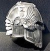
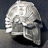
Here's a video showing the cold casting results in more detail. Makes me want to start cold casting everything lol And here are a few more pix of another one I made with a slightly different colour scheme and weathering. The cold cast metal look really comes out nice in this photo. And the plain, anti-climactic inside:
-
While this is not exactly TK-related, I'm posting this here in hopes that the steps I've taken in building this mask (and the mistakes I've made along the way) can aid other DIY-ers out there in their own projects! (Cross posting this from my blog, mynocksden.com) I will never forget the cinematic in Knights of the Old Republic when Darth Revan takes off his mask to reveal your character's face underneath. What an EPIC moment! That scene will forever be etched in my mind as the greatest plot twist in video game history. When the story of Revan was later continued with the release of Drew Kapryshyn's novel Revan and Bioware's new Star Wars: the Old Republic, I knew I couldn't put off tackling the mask any longer! So I built it. To start, I used my trusty old V1 Sith Acolyte Bondo Mold to use as a base, and used Sculpey to create a rough shape of the face. Realizing it would be easier to tackle the visor later, I filled this in, and continued to work on smoothing out the surface. Next, I threw this onto a baking tray and put the whole thing in the oven on 275F for about 70 minutes. While putting Sculpey in the oven is quite safe (and is exactly how you're supposed to cure it), in retrospect, I would NOT recommend putting anything Bondo in the oven. It stinks to high heaven and is actually quite toxic. I did it once, and will never do it again! Anyway, once the sculpt baked, I used an electric sander to smooth everything out. As Revan's mask looks to be made of layers, I decided to use some spare ABS sheets I had lying around to create the features. To make things easy, for each layer of detailing, I took a long sheet of paper, folded it in half, and drew half the design on it. I then cut the design out, unfolded the paper, and got a perfectly symmetrical cutout which I then traced onto a sheet of .06 ABS, and cut out with scissors. I then glued the first layer onto the cured Sculpey using superglue (which bonds really well to it, by the way), and proceeded to do the same fold-draw-cut-trace method with subsequent layers of the features. Next I needed to do the two little speakers (or whatever) at the bottom of the mask. I rolled up some sculpey, cured it with a heat gun, then cut two small pieces at an angle, and superglued two snap button (male ends) to make the speakers (or whatever). (At this point, the snap-button assembly had to be at an angle as in the above photo in order to face straight ahead on the curved mask surface. This will prove a needless set of steps when I later decide to alter the length and shape of the mouth/chin area). After cutting out more plastic pieces and supergluing them on, I ended up with this. Next, I applied some Bondo to fill in the transitions, sanding it down to create some smooth Bondo goodness. Next, I sprayed the whole thing with mold release, and over the course of 16 hours used two coats of Rebound 25 thickened with Thi-Vex to make the rubber mold. And finally, the first cast. At this point I realized two things: 1) the mask was a tad too long, and 2) the front chin section was curved way too much compared to the reference photos. I could have left it as is, but no: it has to be perfect! I cut off the chin, shortening the mask by about an inch. (I also cut out the eye slit just to see what it would look like, though I should have left this untouched for now). I used a little bench belt sander I just bought on clearance for $80, to shorten the bottom trapezoid, careful not to chew too far into the surrounding area. You may notice the curve of the cranium is slightly different from that of the Bondo Mold. This is because I used Smooth Cast 325 resin for this casting, which has a tendency to remain quite rubbery after demolding. This allowed me reshape the curvature of the forehead simply by bending and twisting the resin, thereby letting it harden to correct shape. I used SC 325 for this very purpose: it is a lot easier/cleaner/healthier to bend rubbery plastic into shape than it is to sand a pound of Bondo off a mold to reach the desired shape (which often requires adding more Bondo, more sanding, more Bondo, rinse and repeat). Next, I dremelled some more lines on the mask, filled in a few trouble spots with Bondo, and used a heat gun to curve out (or flatten) the bottom of the face. I then used a fresh pair of snap-buttons to add the speaker (or whatever) detail. I then used a progression of 120, 220, 400, 800, and 1000 grit sandpaper to smooth down the surface to get the thing ready for rubber moulding (again *sigh*). I used a piece of ABS to cover the eye slit from the inside, slapped the mask back on the Bondo mold (after busting off the original Sculpey-ABS master), and used a bit of Sculpey to fill in the gaps between the Bondo mold and the mask. I left the Sculpey uncured. Once again, using two separate coats of Rebound 25 thickened with Thi-Vex, I created a new rubber mold; using PlastiPaste 1, I then created the mother mold. Now I decided to try something I haven't successfully done before: cold casting. Cold casting is a process by which a fine metal powder is mixed in with resin, which upon curing, can be buffed and polished to a real metal look. I've seen it done before, and the effect is truly amazing - if done right, you cannot tell it's not solid metal! So, I acquired 5 pounds of 325 mesh aluminum powder and set to work! Using Smooth Cast 65D as the main medium, I measured out equal parts of part A and part B to about 3 parts of aluminum powder, and mixed it all in a red solo cup. NOTE: though the pictures show only 1 part powder, after snapping the photos, I quickly added two more scoops. I read somewhere that you can add as many as 10 parts of powder, though I didn't want to go that far. Anyway, I didn't have time to take a photo of this as I had very little time left to mix (as technically, the powder should be mixed into part B first, before adding part A). Also, a breath mask is crucial at this point, as the aluminum powder is extremely fine and can be easily inhaled. I dumped this mixture into the mold, smushed it around with my finger to drive out any bubbles, and slush cast the first layer. Since the mask only needs to look metal on the outside, the two subsequent layers were done using 65D without adding aluminum. The final cast came out quite nice. Next, some trimming and sanding, and buffing using #000 and #0000 steel wool, and the mask began to shine! Really happy with the way it turned out! Since the photo doesn't really do it justice, here is a video of the results. Lastly, I used some #000 and #0000 steel wool to buff the forehead, and a combination of various Testors paints to both paint the face and weather the cold cast-metal, and behold the finally completed mask! Thanks for looking, and happy crafting!
-
I got a few of these on order but they haven't arrived yet: http://bit.ly/15IfYRV Also, got two of these to try, but again haven't had time to play with them due to other projects. Look at the size comparison! If it works, both the cost and the footprint of the system can be reduced drastically, which will be awesome!
-
What kind of amplifier did you have in mind?
