


swmand4
-
Posts
182 -
Joined
-
Last visited
Content Type
Profiles
Forums
Gallery
Articles
Media Demo
Posts posted by swmand4
-
-
Good luck, you'll do great!
-
Quick question, Tim. Does your belt plastic have the button covers molded into it? It looks like it doesnt... maybe Rob changed his belt molds?
-
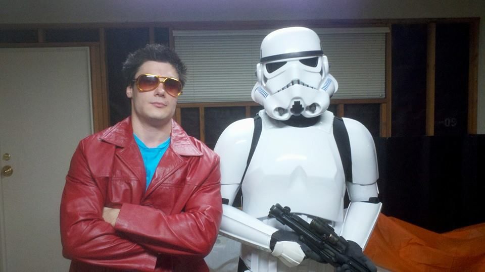
On the front of my own armor, more pictures keep popping up from last Halloween (even 9 months later!) I'm hoping to take my set of approval style pictures this weekend so I can get final critique from all of you fine folks before going for the real deal.
Not happy my thigh ammo pack fell down a bunch - I'll have to put some E-6000 there or something to keep it in place.

-
Just to be clear, Steve, the photos two posts up are Jesse's armor and not mine.
Jesse, I did not have any issues with my shoulders being too far from my shoulder bridges. When I made the straps/snaps connection between the shoulder bridge and the shoulder bells, I had someone help me hold the shoulder bell in place and roughly measure the length of the strap needed. It looks like you could shorten the length of your connecting strap to bring the shoulder bell up and closer to the chest plate / shoulder bridges. This might also bring your biceps up a touch (which also might look a bit better and give you more arm mobility). And, as Steve pointed out, the elastic strap around the bicep should be ~3/4" thick. Otherwise it looks pretty good!
-
Personally, I used 24AWG wire and coiled it around a pen.

-
I was hoping, against all odds, they would stick with the classic ANH stormtrooper for the new movies. But something new could be good, too. Thanks for sharing the link!
-
I don't know about Jesse, but I had to cut quite a bit off my thighs to make them fit better. I also seem to remember taking more off the top than the bottom... page 4 of my build thread has some pictures of it.
-
-
Looking good, Tim. I had the exact same issue with the right forearm; takes a bit of skin off each time. I actually borrowed a Dremel and sanded the ends of the forearms even more so there is no slope down towards the wrist. Looks alright and makes it easier to get your hands through. I'll post a picture when I get home tonight.
-
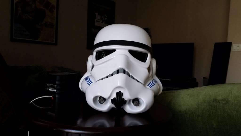
Heh, wish I'd thought to ask Rob to paint the inside of my bucket. Looks very cool. Maybe I'll buy another helmet one of these days...
-
Sadly, I've been too busy with work, life, and projects to get around to getting my TK#. I hope to have some time in the next couple of weeks, though.
-
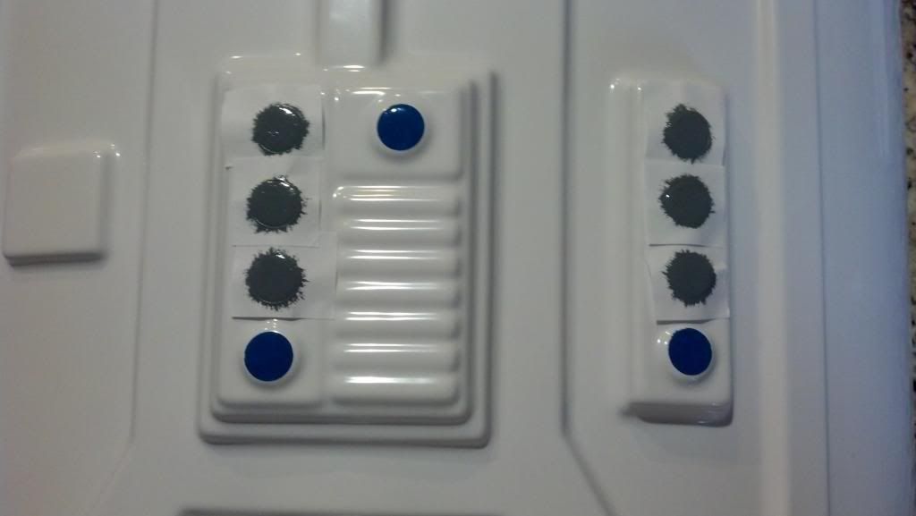
I still have about 99 sheets of the 1/2" circular labels I used as a stencil of sorts for painting my ab buttons. If you want a sheet, send me a PM.
-
Well, things aren't going so great with this project right now
 I cannot, for the life of me, get my microcontroller to communicate with an SD card. Seeing as I've never done this before, I don't know what exactly the problem is. I do know, however, that based on the 2K of RAM the AtMega328P has, I will either need to change microcontrollers or ditch the FreeRTOS. There simply isn't enough RAM to run both an RTOS and an SD card (as I understand it, an SD card reads 512 bytes at a time, or 1/4th my entire RAM). For now, I will prove the rest of the design works in pieces and then make overall system architecture changes later.
So then I moved on to SPI comms with the audio decoder chip... only to discover a pitfall involving dual uses of the 328P's reset pin. Long story short, I have no usable chips and will need to hack up a board to make it work once I get more. As I said, I will need to prove that the pieces work before moving on to redesign. I should have new MCUs Friday or Saturday.
These two mistakes are quite embarrassing as I do some of this for a living. However, I use entirely different chipsets, peripherals, and tools at work. So a lot of this is a learning experience for me...
As of now, I know the barrel LEDs (red&blue, but not green) work, high brightness RGB barrel tip LEDs work, ADC battery monitoring works, and the trigger (sort of) works. I still need to prove the SD card can read an MP3 file, the audio decoder chip can receive that MP3 and then play it, the green barrel propagation LEDs work, the power level bar graph works, the volume control works, the vibration motor works (should be relatively easy), the battery charge controller works, the select button works, and the fire rate selector works. After that, it should be all software and fine tuning.
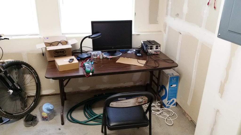
At least I have a lab bench set up in my garage. It's something.
-
Hey man, congrats on getting your RT armor! Can't wait to see the build pics start coming in.
-
Been a long time since I posted in this thread...
Finally got around to painting to vocoder and ear rank stripes on the helmet. I messed up the vocoder my first past as I'm not very good at painting, but was able to touch up my mistakes using a Q-tip dipped in paint thinner. Then I just repainted the parts that needed it, except more carefully. I'm not 100% happy with it, but it's better than I expected and it'll do. I'm also not perfectly happy with the ear rank stripes, but there's no fixing that without messing up the grey paint.
I AM, however, happy with the camera in my new cell phone

-
I have RT-Mod and love it. Plus Rob ships the helmet already completed, so the toughest part of the build is done for you. I'm about 220lbs and 6'2", and had to cut a fair amount off the ab and kidney sections. Don't know if that helps you at all...
-
Another piece of groundwork finished: The I2C drivers for the barrel LEDs is working. I spent hours trying to find out why I couldn't read the LED driver chip's registers back for debugging when I figured out this chip is write-only. It cannot respond to master commands.
If you thought the last picture was a mess of wires, take a look at this:
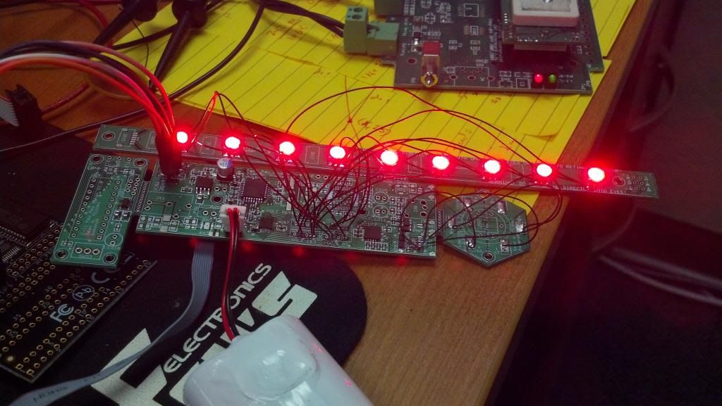
Another step closer, but still a long way to go...
-
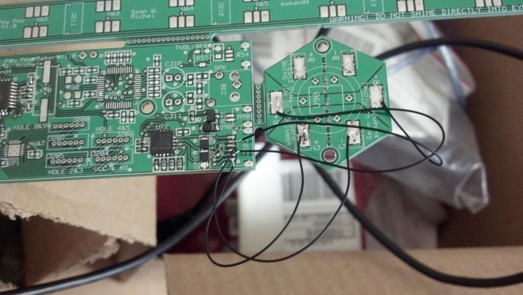
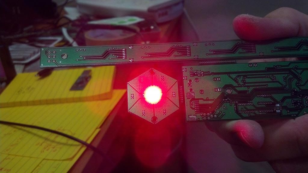
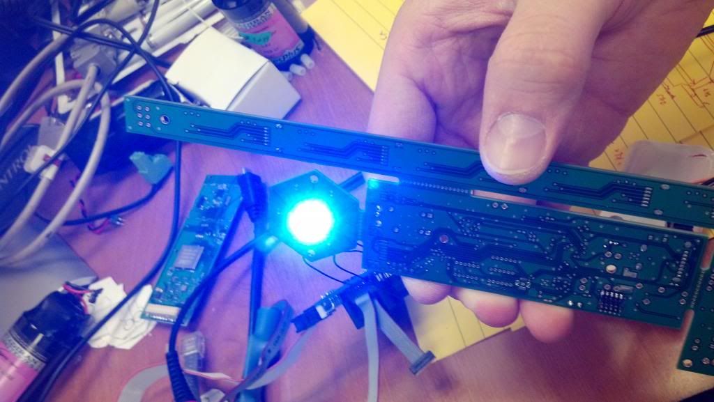
A little more progress today. I discovered an error in my PCB design (!) where the power transistors for the high brightness LED were mirrored. Stupid datasheet broke convention and showed pin orientation from the bottom of the chip instead of the top... So there will need to be a PC board redesign and round two of ordering at some point in the future. I'll need to finish testing other parts before I do that in case there are more mistakes. For now, I have a work around that just rotates the transistors and hacks them in place. Red and blue work, but green does not and the firmware code to turn on blue is labeled "green". Oh well, works for now. See for yourselves:
-
Just a quick update tonight.
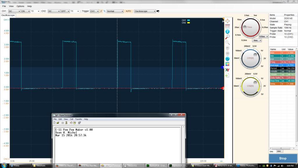
I have the UART up and running for printing debug information to my screen, the ADC channels sampling correctly, and the pulse width modulation (PWM) working. I'm slowly building the infastructure needed to put the whole thing together. Various other pieces of code are starting to come together as well (trigger pull function, audio level, config button press, fire rate / stun select mode, etc.). Up to about 755 lines of code now.
Getting the PWM to work correctly was a pain in the butt. Turns out I accidentally took a semaphore twice just prior to initializng PWM which cause some undefined behavior. All good now, though
I'm also working on getting a home lab set up with a solder reflow station, soldering iron, oscilloscope, DC supply, etc. so I can work on this at home as well. Should speed things up a bit.
-
I was going to do the same thing with my Hyperfirm DLT-19 and E-11! How did you mount them on your wall?
-
I think that's what I used. Works great. My only recommendation is that you fold the ends over when you place your snaps through it. That way the stem of the snap goes through two layers of elastic and is less likely to pull through or fail over time.
-
why must my suggestions always meet with criticism?
I'm a musician.. and I hear mono as mono...? other blaster setups actually have stereo sound?
so why not this project?
gee... I guess mono must be better for most people...
sheesh?
blastercore setups I have seen have 2 speakers... one in the pipe... and one in the counter..
but I guess I'm just not paying attention?
X citer... hmmm...
i guess mono is fine... ahhhh... does not really matter after all...
hmm...
not like my opinion really matters anyway?
Vern, my board supports stereo sound. It's fairly easy to swap the resistors around to enable it, and I'm purposely using a standard sub mini stereo audio jack to allow for it. Please read my last post where I actually (albeit indirectly) support your views on stereo sound. Your opinions are valid and being heard.
The audio decoder chip outputs stereo by default and I combine the two channels into a single one with external resistors. I'm not sure if this makes the output to the speaker louder or not, but that's something for the experimentation phase.
-
About the name of the project, borrowing from Wookieepedia, I suggest "Xciter". It's an exciting project, that makes the prop more exciting for everyone near it, and it sort of fits with it's description on wookieepedia. Plus, it's more catching than "Actuating module", although that part of the fictional blaster is slightly more accurate to the reality.
I love it! XCiter is my new front runner for final product name. Thanks Mathias.
oh man... that speaker looks great! would only one be used or 2 in stereo?
any info on the location to purchase a couple?
would you be willing to wire up a blastercore 4.0 for me? I'd pay?
I've designed the board to have optional stereo sound, but it will be defaulted to mono and require SMT rework to change it. I did this to allow for a flexible product - maybe someone wants to use two speakers for a special effect. Or maybe they won't be using it for an E-11, but rather for a longer weapon that would sound better with a second speaker further down the barrel.
I actually linked to the Amazon page where I purchased my speaker a few posts back.
Sorry, Vern. I don't have the time to wire up a BlasterCore for you. I have my own version to finish

-
Thanks for the kind words, everyone. Positive feedback always helps
I think I've decided to ditch the external oscillator for the ATMega328P. I'll just use the internal RC 8MHz one. It's extremely inaccurate and susceptible to temperature change. But for this application, I am using SPI and I2C communication methods, both of which supply their own clock. I'll have to use a slow USART speed for debug (9600bps) but that doesn't matter for the final product.
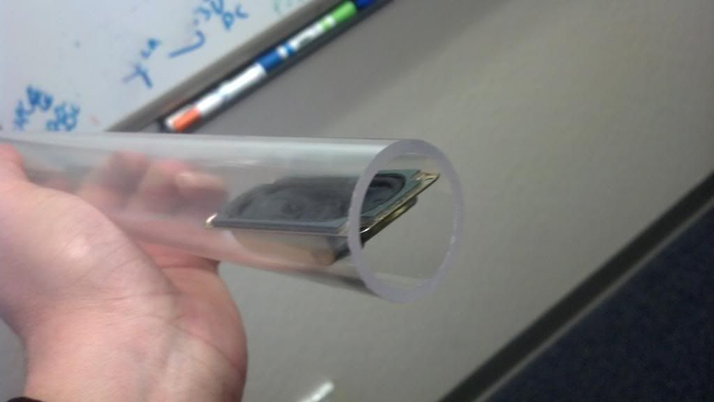
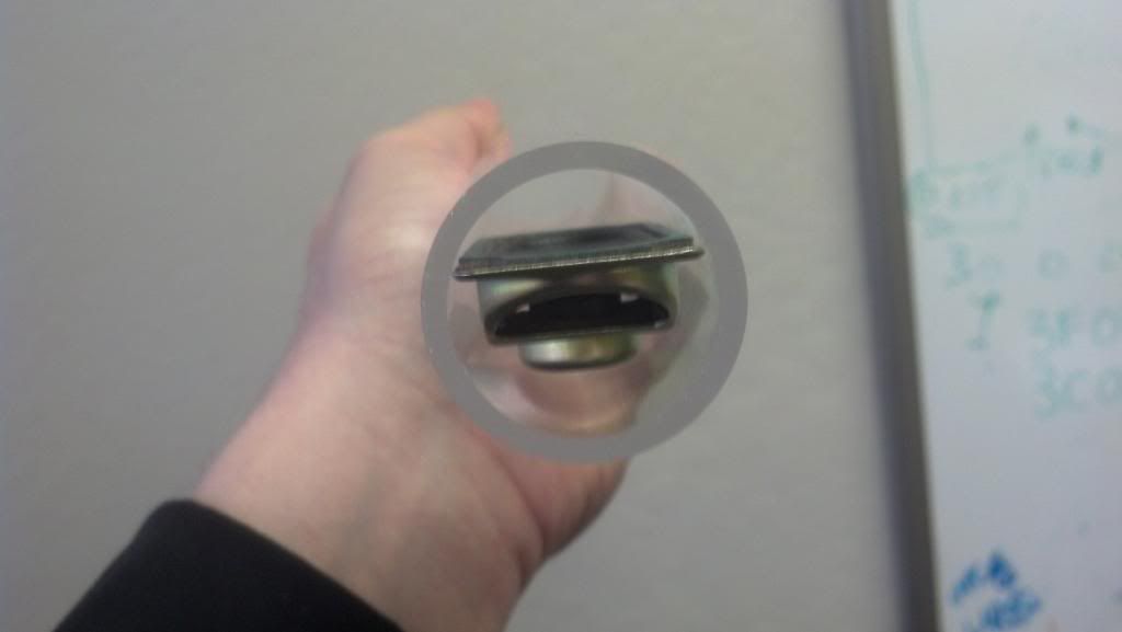
The speaker came in today and seems to fit well. Pictures below:

Building An Alternative to Blastercore: E-11 Sound/LED Board
in Build Threads Requireing Maintenance
Posted
To be honest, I haven't worked on this in a long time. I still want to finish it, and might get some free time about a month to resume prototyping and coding.
I don't suppose anyone knows anything about reading an MP3 file off an SD card using an 8-bit micro-controller?