
.jpeg.ff3078cf696d324fa576c149490ede78.jpeg)

themaninthesuitcase
-
Posts
4,121 -
Joined
-
Last visited
-
Days Won
31
Content Type
Profiles
Forums
Gallery
Articles
Media Demo
Everything posted by themaninthesuitcase
-
 Given the nature of the issues and details involved: no. I was one of the staff who investigated and I can only say to you I was as through as I could be and it was corroborated by other staff. We are confident in our decision and stand by it.
 -
New costume coming to FISD New section NOW OPEN
themaninthesuitcase replied to Sly11's topic in Announcements
It wasn't a vacuum. Detachments where asked to "bid" for the new CRL. We, as staff, put together our case and justification which the Detachment Leader presented to a Legion committee. I am aware of at least 1 other detachment that did the same. After going to the Legion our case was deemed better so we got the CRL. This would require both detachments to agree, and I believe all active members of that costume to agree. Which is probably unlikely. @Sly11 will be more aware of what would need to happen. -
Where to mount a Voicebooster amp in a TK
themaninthesuitcase replied to Alikh's topic in Electronics for Helmets / Blasters
I also have mine mounted in the chest, in one of the peck sections. It's held on with 2 small strips of velcro, never had an issue with it coming loose. -
TK-23108 reporting for duty
themaninthesuitcase replied to BAZINGA's topic in Newly Approved Members - Sound Off!
Welcome to the FISD! -
Welcome to the FISD William. Looks like you're not a million miles away so hopefully see you at a troop soon. If you're interested consider applying for the level 2 (and 3) approvals. https://www.whitearmor.net/forum/forum/95-expert-infantry-program/
-
How to add a hyper link to signature?
themaninthesuitcase replied to BAZINGA's topic in Forum Help & Support
The other option you have is to use something called BBCode which uses square brackets. Link using just the url [url]https://www.whitearmor.net[/url] Linking using text [url=https://www.whitearmor.net]The best detachment[/url] this will come out as: Link using just the url https://www.whitearmor.net Linking using text The best detachment -
Wednesday Update! I've been working on the D ring I picked up some 32mm rectangular loops, I think for bag straps, from eBay. They are 32x19x5mm. To make this work I have adjusted the swivel cap to make it notched so the ring just drops in and is then secured between the swivel cap and end cap. I then cut a small section from the D ring This all then mounts using a 10mm long M3 cap head screw. Looks great? Nope looks way too big. You can see it's way too long, and a bit too chunky. Time to pixel peep the reference: It's not great resolutions but I think the diameter is more like 4mm. The internal measurement looks like it wants to be about 15/16mm. So it's not actually million miles out, though at this scale small differences are a bit obvious. I've just been hunting and found some new loops that seem to be a better match. On to something else I've been working on. Pew pew noises. I got some new parts. The new development board is a Teensy 4.1. This is a significantly more expensive board than the import nano I was using, about 10x more. But it is also far more capable. I have paired this with a small 3W DAC that takes the digital audio from the Teensy and put it out into the 28mm speaker, which is the same sort of size used in lightsabers I think. After a few worrying moments where I thought I'd cooked the board, but turned out to be a bad bread board, I ended up back where I was before with the old setup. I added a 3rd trigger option, currently I imaging I would use this to run the torch from the switch in the front. I don't have to but once hardware is made you can't change it, software is easy to change. The audio wasn't too hard to add, once I read the examples anyway. The default amplification is reasonable, but can be significantly increased if wanted though I found this was distorting the small speaker I have. The basic concept proven I went back to the PCB for this all to go on. The biggest concerns are it needs to be small, and I need to be able to get the SD card out still. This means I need around 10mm clear after the teensy. This is roughly where things are. The capacitor will be laid down to save space. This smooths power in moments of sudden high draw, like say turning on 21 neopixels and a 1W LED all of a sudden. I may or may not use the JST-XH connectors. It will make removal easier, but they are also a bit bulky. Soldering would be more reliable but more of a head ache, JST-PH are also an option, smaller but have lower current capabilities, which will matter on the 4x one as that's going to the external power switch on the side of the magazine. I've opted for small surface mount parts to save room, but will be a pain to solder. To make life easier, all SMD are the special hand solder variants to give a bit of a bigger pad to solder to. There's not a lot left to do on this other than "draw the rest of the owl", that's a reference™. I have a few final details to add to the 3D model. Somewhere flat to attach the neopixels to the barrel, somewhere to mount the speaker and I have an idea to help focus the red light for the mag and hengstler I want to try. Once that's done, I can start printing bits, order some PCBS and do some test building of things.
-
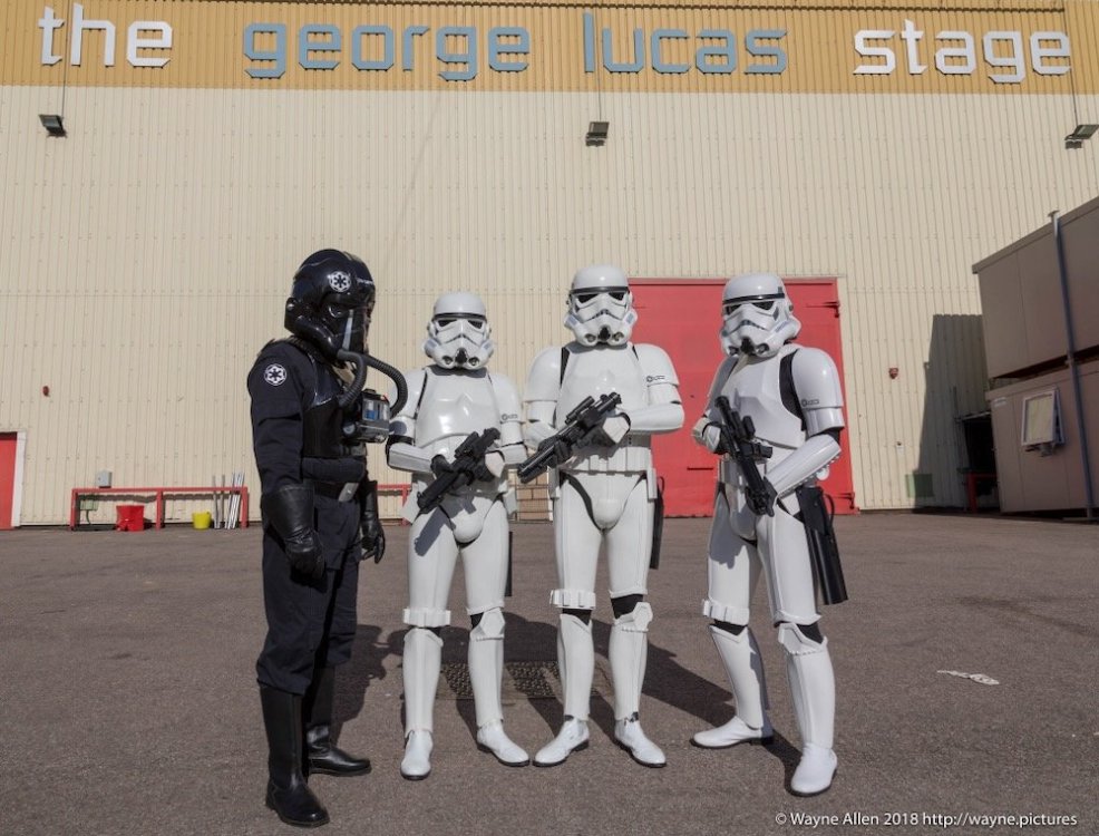
It is with great sadness I am making this announcement that today we lost one of our own. Earlier today Dan Branton TK-42911 passed away, after a long battle with cancer. Many will know him for his incredible enthusiasm in always helping others and this often included aiding those to build the best stormtrooper they could. Within his own Garrison he held the position of armourer. A formal recognition of his enthusiasm, his knowledge, and his ability to assist others new to Star Wars Costuming. Here he was a staff member, a Provost Marshall, and his opinion always welcomed. The majority of you will only know him from the forums, or Facebook groups he would post in. To many others, myself included he was a great friend, and we will miss him dearly. He is succeeded by his wonderful wife Tuesday and their three children. Buckets off. Dan Branton, left most stormtrooper, pictured trooping at Elstree Studios near London in 2018.
-
Themaninthesuitcase SE-44C build
themaninthesuitcase replied to themaninthesuitcase's topic in Weapons of the First Order
No, for the year is 2023. It's finished. Well close enough anyway. I managed to prime the side cover things last summer, and looking at them last week I realised all it needed was a rub down and they would be okay for top coat. So during the week I've been sneaking up and rubbing them down with 400 and then 600 grit. Possibly a bit rough and ready, but take a look at real film props up close some time and see how rough they can be. In the end it came out nice. First job gloss paint. Always a phrase that fills me with dread. Took it slowly, a light dust coat and then a couple of wet coats to get a nice smooth finish. It's not flawless but you'd need to be pretty close to tell. Assembly was a bit scary as the paint probably could have been left another day or so. However I know that I need to do things when motivated or it will be another year or so loop. I started by using a scalpel to clean off paint where parts will glue and the barrel nozzle fits. I should have masked these but a blade works if you're careful. The top sight was assembled using M4? countersink screws. IIRC the original instructions wanted to use a grubscrew into the Glock slide but this felt like a better solution to me. The mount bracket was countersunk to accept them and then everything was done up to approximately "snug". The sight is resin, the mount PETG and doing things up too tight will just break things. At snug they should stay done up, and not strip out the threads. The top black thingy no longer fitted. Paint tolerances are a nightmare, but the fix was simple. I applied a bit of masking tape to the face of the file to make it safe then used the side of the file to add the needed clearance. This done a dab of Tamiya Semi-Gloss black was added to hide my crimes. The sheen is nothing close to the spray Satin Black I used but it's close enough for this. Next came bolting things up. The instruction PDF was long gone at this point and the one in the TFA download is for the TLJ build so some educated guessing was needed. I have a stash of M3 and M4 security Torx screws in assorted lengths, as you do. I used the TLJ guide to get the size and then picked the appropriate length by holding them to the part. I used the longest possible for each to get a solid join. The most important was the front M4 screw as I am actually using this to join the two halves, no glue. The longest I have went about 10mm into the other half which should give a solid fix, and on the other side the shortest one I had was used as it's effective decorative unlike the rest. The last job was to glue the red thing onto the sight, glue in the slide pull, barrel nozzle, and the sight into place. All of this was done with the smallest dabs of CA so not to make a mess but also give me a sporting chance that this semi removable if needed. Hooray pew pew time. I do need to add the holster bracket still. I have an idea for this but I need to get the hole spacing and hardware size for the R2Dan holster so I don't screw it up. -
Greetings from Berlin … Germany
themaninthesuitcase replied to TK 26476 - Marz Elson's topic in New Member Introductions
Welcome to the FISD! -
Bit more work this week, though not as much. The hinge fits both the submicro and normal microswitch. They have a different feel to them. The submicro is very light but the standard is pretty solid. The front screw for the grip is just in the right spot to act on the micro switch. For the small switch an 8mm screw is about right but for the fill size the standard 6mm is the one you want. At least I think, I need to mount the hinge to the under barrel to be sure. The mounting is slightly different between the 2. Both use M4 grub screws, the smaller just one in the middle and on the larger 2 fit into the mounting holes on the microswitch. It's a little more visible than I'd like when the front grip is hinged down but given you'd probably be holding it I think it should be okay. Maybe swapping to a non-lever type could fix this, but may need a little "button" added to the grip. The screws will face "in" towards the body so even when hinged down they shouldn't be super obvious. I also hit a wall with the audio on my effects unit. Basically unless something is already playing the lag on DFPlayer Mini is far too long (between 0.5 and 2 seconds). I spoke with some one who knows what they're doing in this field and they said they spent ages trying to work around this a while ago and didn't find one either, so went another route. So another route is to be taken! I have picked out some new parts, which I have yet to order as they are a fair chunk more expensive than what I was using. Well the main board is about 8x what the nano clone costs, the audio board isn't actually too bad. News when I get further I suppose.
-
We're not making Disney park suits, which have several other concessions to accuracy. For reasons of comfort, service life and presumably ease of manufacture they are quite different. We are making film accurate suits. This is not hyper focus, this is the 501st doing what the 501st has always done. Make the most accurate costumes we can at any given moment. That last bit is important, and the reason why initially it was allowed to wear ANH style boots, because there was no other option. Now there is an option, and the CRL no longer allows for the older style boot. As resources improve, technology improves we get better at making them more accurate and the standards rise along with that. The CRL says no visible seems. The old Anovos kits had a seem that need filling, these kits need a seem that need filling and iirc so did all the other ABS based kits. 378* "pre-production" "Anovos" kits where made and presumably a reasonably number of them where completed, and so had filled seams. Then add the kits for other vendors. Is the seam a huge ugly thing that stands out a mile? No. Will some GMLs approve it anyway, it wouldn't surprise me. But filling 4 seams is not the huge headache people are making out. Unless you don't wear proper PPE and work in a ventilated area. We have it good here: 4 seams to fill and some glue, there is even actual instructions for all of that bar the filling. And a decal sheet! Now consider other hard armour: a Shore trooper, clone, death trooper, scout. All of those are so much more work, and have all their own set of issues with stuff breaking. Fill the seams, this is the way. *according to who made them, but with out double checking their notes.
-
Need help with sound and light project
themaninthesuitcase replied to S. A. H.'s topic in Electronics for Helmets / Blasters
Given you want to trigger lights as well as sound then a simple audio trigger board it off the table. I would probably start with an Arduino, I tend to use a Nano as they are small and cheap but there are new better options really these days for not a lot more. Audio has a few options. Items to consider are the DFPlayer Mini, Adafruit and Sparkfun also have some options. The DFPlayer is small cheap, but the one I have is a clone (so even cheaper) but it seems to have some issues and I want to try a real one when I can get hold of one. Lighting wise Neopixels (or the various products that use the WS2812 LEDs) are a solid pick. You can do all sorts of stuff like fades, streaks, pick individual pixels. Very powerful, but you do need to think through what you want to happen and how that will need to be coded to achieve that. -
Still poking 1s and 0s but also worried some plastic today. I wasn't happy with the solution I had for the front torch. It was inelegant and required cutting up a torch that was really a bit too large. So I went back to the reference: A photo of a screen used TFA item sold at auction (see the gallery) So what we can see here is the torch pokes out through the silver cap slightly, and seems to run the length of insert. It also seems this is friction fit and fine tuned with duct tape. Standard. So our options become: Try find the original part Germain spec'd, but has been out of stock for years. Find another torch: There is the "AtomLight" but this actually looks too small and the light sounds a bit dim anyway. The Maglite Solitaire LED looks to be about the right diameter according to the specs but is pretty long. A new "Folding Stock 2 - Flashlight 1" would need to be designed that doesn't need the screw to hold it using friction or a click fit, and to allow the torch to extend back into the blaster further. With a screw you wouldn't be able to remove the holder to change the battery. Whole arse a custom solution using of the shelf parts and can hook into the power for the lights you need anyway. Obviously I chose the latter, but may get a solitaire anyway to try. I have a number of LED bezels lying around, like any normal person and decided to try using one to mount the ultrabright 5mm LEDs I bought ages ago. This is what I ended up with: So the Bezel holds the LED in place solidly, the back of the mount has mostly been removed to give access to fit the LED. A "fake" torch sleeve fills the empty space and a 12.5mm glass watch face creates the look of a real torch. I hope anyway. I had the afternoon off for an appointment so ran off a set of parts and quickly threw some paint on to show contrast. Sand your prints people, this is just proof of concept stuff. Front view, I might paint the inside of the inner collar silver to lighten it up a bit and reflect the light. Side view, there is no lens here so add about 1mm of extra length to the black ring. After seeing this I felt the lens was too far back so have moved it forward 1mm so its not so set back. And finally the most important feature as this part is actually oriented and I keep getting it wrong. I think this is going to work out. It will look close to the real one, certainly for a casual look, and still give the the ability to switch it with out twisting the end. Be that via the front grip or an other switch. Still TBD on that one. Making it just "passively switched" vs "actively switched" in software controlled would free up a decent amount of real-estate on the board but on the other hand more control more better and you cant change hardware later.
-
Test print time! The theory works! This is some 7/0.2 stranded wire which is in the 24AWG ball park. It says the OD is about 1.2mm but which means 0.8mm clearance but the curve makes it a little awkward to thread. You can thread the wire both directions but you need to use tweezers to do it from inside the well which is a little tedious but means it's not un repairable if a wire breaks in an awkward place. If you're extra fancy use PTFE coated wire, it's a little stiffer so once the initial thread is done it slides easier and pushes better making the process less awkward. If you haven't tried some, it's pretty cheap on AliExpress just plan ahead. I don't have a switch as mentioned before but it all looks okay from this side. You can see the very tiny M4x3mm grub screw I have that will work nice to hold the switch but not stick out. a M4x4mm should also fit, and I have in stainless steel which will blend in better on a finished piece but that means moving stuff to get to them.
-
I've been carrying on poking the 1s and 0s around. I think I have managed to fit a micro switch into the front hinge of the blaster, well actually a "miniature" microswitch which is a decent amount smaller but can still take 3 Amps so hopefully will be up to the job. The idea is this can work the front torch rather than using triggers to do this. Fitting the switch was not too bad, but getting the wires out was harder. I've opted to run two small tunnels either side of the mounting screw and through into the box section of the front stock, which then can run up into the barrel before entering the hollow core of the blaster. The switch will be held in place by an M4 grubscrew, so should it fail it can be removed and replaced without worrying about glue. You can also see on this image 2 location pin holes I added as I struggled to line this part up on my unfinished blaster. This is just 2 1.75mm holes for some filament offcuts. I still need to order the switches and check fit but it should work and gives a nice option for a switch in a place that makes sense. I also struggled with getting good results sanding the Magazine end cap, so I broke it into 2 parts. The main cover, and the button. In theory you could also make this a working button but I've not done that. Yet, I suppose you could do it with a tactile switch stuck through the cover. It should be about the right size. Finally I have also been working on full lights and sound setup, because apparently I needed more work before I can call this finished * I have based this on an Arduino Nano as I have several to hand and they are cheap, a cheap DfPlayer audio board, an old laptop speaker but want to try some others, a 1 watt 6 Pin RGB, some neopixels and 2 switches. The current working setup has a primary trigger that fires a blast, and a second that toggles the front torch on an off (Yellow LED in what follows as the white one was annoyingly bright). A blast triggers the sound effect, sends a streak of down the side that has a short dimming tail to help convey the motion, and blips the Red part of the front RGB holds it very briefly then fades out quickly. Again this attempts to convey motion and cool downs. The main issue I have is the audio lags by up to 1/2s. If you keep audio running, each new trigger is instant, but from a cold start there can be a big delay which won't do. I am wondering if this could be the fake DFPlayer board I have, but I don't really want to pay 3x the price for a real one due to handling fees at the vendor. More work on this to follow I am sure. As mentioned the 2nd button toggles the front torch but now I have a front switch this leaves it open to other uses which I've not decided on yet. Plus the option for the extra button on the magazine cover, though if I'm not sure what to do with 2 what would I do with 3? Nice to have hardware that can be expanded though if I can make it fit. I also need to work out if the torch should remain software driven, or if the front switch will just do that directly and so simplify things a little. This will all go on a custom PCB designed in KiCad and which will be available publicly, along with the software. The software is already if you know where to look The JST XH headers, are bulky but give a degree of ease to assemble as you can do all the soldering away from the easy to melt blaster. They may yet still go away, especially if I want 3 switches to read in software as well. And as a reward for reading all of that drivel here is a demo of the blaster and it's all important hidden mode. Sorry it's vertical I made it for the gram. * I am aware the irony of using the word finished in a thread that dates back to about 120BC
-
I would laugh but it's true my F-11D build is now over 5 years long, and my SE-44C getting on for 6 and here I am thinking I should just start over on both!
-
Sorry meme in payment:
-
Good thing I forgot to ask about them then as that would just rub salt in the wound.
-
Borrow a storm trooper uniform
themaninthesuitcase replied to Jay Donovan's topic in New Member Introductions
This is why we are here, troopers helping troopers. Start by taking a look in the getting stared area. Lots to read up on and get you started, then once you have some specific questions we can go from there. Good places to start are and -
Celebration 501st and FISD Group Photos
themaninthesuitcase replied to gmrhodes13's topic in Announcements
Wayne was the Legion Photographer so these are the official photos. -
Whilst not Florida hot we now get our share of warm weather now. I’ll iterate again the secret is to Hydrate the day before and then manage it appropriately on the day. It’s also worth remembering it’s not just the sun to worry about. Convention halls can get hot when full of 1000s of people and you won’t be paying as much attention as you’re inside. And don’t be a hero. When you’re done you’re done, there’s no shame in that.
-
-
Found it! Got to EIB 828, Centurion 399 so it’s pretty out of date now.

