


Troopacoola
-
Posts
1,029 -
Joined
-
Last visited
-
Days Won
18
Content Type
Profiles
Forums
Gallery
Articles
Media Demo
Posts posted by Troopacoola
-
-
Can you post some pics up of the arm Rodney? I'm pretty sure yours does have the semi hollow arm with the recess for the arm clip. Here is a pic that had been shared both here and oin the JMC FB group


Sent from my SM-G950F using Tapatalk -
I think it's called "Green Stuff" in the States. In the UK I use milliput which is a 2 part epoxy putty.
Sent from my SM-G950F using Tapatalk-
 1
1
-
-
Lots of cable running out of that lid. Could you not reduce this?Ongoing helmet fit-out:
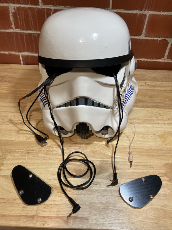
Electrical component functionality test completed:
1] Helmet fans fitted
2] Hearing assist test successful
3] Voice system with iCom test 90% successful - some feedback when running amp at 100%. I bought a $50 pair of Sony headphones, trimmed off the over head loop support and velcro'd them in. They sound output is great - really happy with the cost and performance.
Component physical install:
1] All hardware fits well with plenty of space to spare
2] Cabling routes to be finalised
3] Cabling route covers to be finalised
Am using velcro to cover the cable routes with a still to be determined fabric/material fixed to the back side of the velcro to make inside of helmet look cleaner.
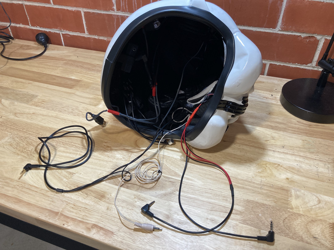
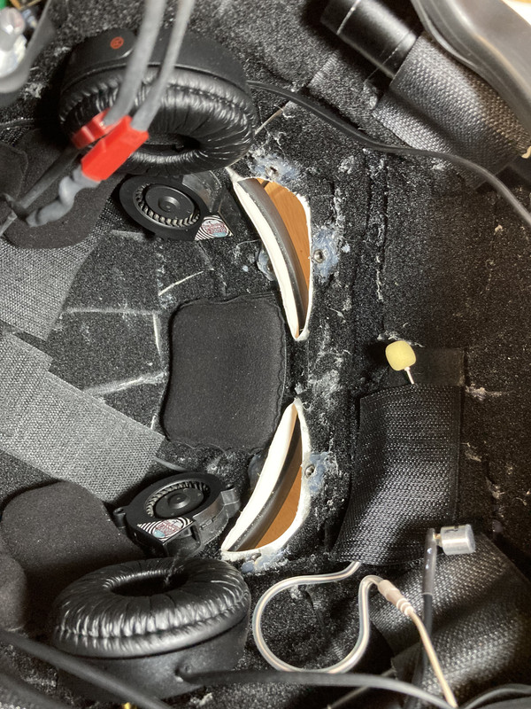
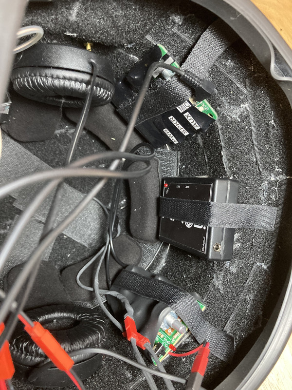
Sent from my SM-G950F using Tapatalk
-
In addition to the BlastFX system I have been experimenting with the addition of smoke effects...
Sent from my SM-G950F using Tapatalk
-
6
-
-
Here is a quick vid of BlastFX in action...
Sent from my SM-G950F using Tapatalk
-
3
-
-
For those who are adding BlastFX here is how I fit the board and wiring loom...
The power switch is fitted in the mag housing and the battery and charging port is accessed by removing the end cap.


Sent from my SM-G950F using Tapatalk-
1
-
-
Thank you!Great mod with the selector, nice work
Sent from my SM-G950F using Tapatalk
-
Back to the ANH E11.....
The trigger assembly the most solid resin piece in the kit. Saying that, there is still no need to grind any resin out as there is plenty of room to fit the trigger. There is a great tutorial on this in the Blaster ref Guide, which is how I fitted my trigger. A nice little extra is that by following the ref guide you can have a working trigger function with the aid of the small spring which is included in my kits.
The grip was cleaned up and the hex bolt fitted. in this case the bolt is resin. However, I supply all replacement metal bolts and screws etc in the kit.
Next was to drill out the hole for selector switch. If you wanted to have this functional you could always drill the opposing side, fit a small bolt into the switch itself and then fill.
With a little more work, you could even install a rotary switch to add that "click" to the selector. This is a really good feature and works a treat and is also an option that BlasFX offer. In this example the selector switch for BlastFX are shown. I have also added an example using black and beige resin parts assembled so you cam see the components, along with my method for adding age.
Once the trigger assembly was complete it was time to fit the grip.
The grip slides nicely on to the assembly and is secured with adhesive. Once dry, the holes were drilled into the assembly (indicated by the holes in the grip) for the almost final components. The metal grip screw and "cap" were then installed.
With the trigger guard installed this assembly is done.


Sent from my SM-G950F using Tapatalk -
Sorry for the lack of updates. I will post more soon! In the meantime here is a sneak pack at the Pugman style ESB kit I am working on making. Some of these parts are reworked casts from ( and with permission from ) Mark at Shear Tech .


-
4
-
-
The grip is a direct cast, so the internal features are exactly the same as the original. I drill the hole out with enough depth to accommodate the hex bolt and then glue in situeThank you Sir! Did you find there was enouph material left to put a nut on the inside? Or just glob it with glue down in there? I've feeling there won't be much material left on the inside for any threading. That screw hole kind of cones outward on the inside.
Sent from my SM-G950F using Tapatalk
-
1
-
-
A 10mm bit will open it upI didn't see how you handled that hole on the underside of the grip. Not sure how to go about it, what drill size or what the deal is with that. Loving your build and using it as a guide as there are no instructions. Thusfar I've found this can take a very long time to build putting just a little time in with it over a period of time.

Sent from my SM-G950F using Tapatalk
-
2
-
-
Another easy assembly. Drilling out the rear of the D-ring mount allows for fitting.
Then it was just a case of installing the ring mount to the end cap.


Sent from my SM-G950F using Tapatalk-
2
-
-
Here is how I do my weathering effects .Looks amazing Dan. Very impressive.
Have you made any videos specifically about weathering? I've recently received my SE-14R from rdr, and it's amazing, but looks far too clean
(If you consider in person workshops I'm keen and will bring snacks )
)
After priming and spraying silver, I do several layers


Sent from my SM-G950F using Tapatalk
-
5
-
-
This^^^
Ooo, can’t wait to see your build, Tino.
Sent from my SM-G950F using Tapatalk
-
1
-
-
I would recommend painting the bolt ahead of installation. However, masking it off once fitted is no biggie.
Hot glue or resin putty can be used to hold the bolt in place whilst you apply adhesive.
For the more adventurous I am sure that making this functional would be possible with some small mods!
The charging handle will have a small post drilled into it and then fitted to the bolt with some adhesive
Sent from my SM-G950F using Tapatalk-
1
-
-
Another little diagram...

Sent from my SM-G950F using Tapatalk-
1
-
-
The mag was just a case of selecting the length I wanted and cutting. Once happy with the length the side clip was then installed into the correct position to stop the mag going any further into the housing.
The end cap was fitted with the release button (5mm LED to you and me!) and then glued onto the magazine.
The mag housing can be easily converted to have a working release. I would recommend that if this was a task others wanted to undertake that this be done after sanding to fit the receiver, but before fitting it to the main body.
Here is a quick demo of the working release...


Sent from my SM-G950F using Tapatalk
-
1
-
-
Onto the cylinders.
First off is to drill a small hole in each of the resistors. Crimping the end of the resistor wire and adding a dab of C/A glue will hold these in place. The length of the wire will be trimmed later.
With the resistors glued in place the next port of call is the actual cylinders. Each cap had a hole drilled through and the respective nuts and bolts fitted. Again, C/A glue will hold these in position.
With Three holes drilled in the plate for the resistor wire I began to fit the cylinders.
Glue one end of the caps onto its cylinder and thread the Cylinder through the hole in the mounting plate.
Fixed in place by adding a tad of adhesive to the mounting arm at the front and a dab underneath the cylinder where it meets the mounting plate.
I fit the resistors and thread the wire through the 3 holes in the mounting plate. Once I was happy, I trimmed of the excess wire.
At the rear, I shaped the 2 resistor wires and clipped off the third and then removed any excess. The red cord was then added. Another dab of C/A glue and some heat to seal the cord and we are done.


Sent from my SM-G950F using Tapatalk-
1
-
-
All parts were glued in place and any gaps filled with.....Erm....Filler!
Quick note:
Ensure that the front sight guard, and rear sight are facing the correct direction!
Sent from my SM-G950F using Tapatalk-
1
-
-
Regarding the resin components being fitted to the receiver, the easiest way to get a nice fit is to wrap some sand paper around the receiver and sand back the resin on these parts to make a nice contact with the camber of the blaster.
I also drilled out the resin hex bolt in the front sight and replaced it with the metal one.
Here is a list of all components that were sanded using this method:
Front sight
Front sight guard
Bayonet lug
Flash guards
Mag housing
Trigger assembly
Rear sight
Rear cap release housing


Sent from my SM-G950F using Tapatalk-
1
-
-
As you can see the front muzzle does not have the resin hex bolts as a part of the cast. Once fitted to the barrel metal bolts will be added.

Sent from my SM-G950F using Tapatalk-
1
-
-
Drop me a PM[mention=13824]Troopacoola[/mention] Is your kit available without the barrel? I already have an Aluminum barrel which we had a series of them made here, and were resin casting parts from a real sterling but the guy with all the parts sold them off unfortunately so I never got to complete it
Sent from my SM-G950F using Tapatalk
-
Here is a quick diagram of how the locking system for the stock works. I would replace the ABS posts for aluminium if I were to make this functional.

Sent from my SM-G950F using Tapatalk-
1
-
-
Following on from that, the front ABS post was inserted through the handle, leaf spring and clip.
With the stock pretty much done it will be fitted later in the build.


Sent from my SM-G950F using Tapatalk-
1
-
Troopacoola's JMC E-11 Folding Stock Help
in ANH BlasTech E11
Posted
The arm will need hollowing out some in order to accommodate the spring and abs tube but not all the way down it.

Once that's done dry assemble the folding stock and dry fit it to the blaster. You can then line up and mark on the arm where you need the clip channel to be. Use the hole at the front underside of the barrel as a guide. The chanel only needs to be around 10mm in length. Drill out the channel and sand down.
Sent from my SM-G950F using Tapatalk